
Interbody spacer

a technology of intervertebral spacers and cages, which is applied in the field of spinal implants, can solve problems such as pain, compression or irritation, and stability problems, and achieve the effects of improving stability, reducing pain, and improving stability

Active Publication Date: 2021-04-20
NEUROSTRUCTURES
View PDF277 Cites 2 Cited by
  • Summary
  • Abstract
  • Description
  • Claims
  • Application Information

AI Technical Summary

Problems solved by technology

In such cases, pain typically results from compression or irritation of spinal nerve roots arising from reduced spacing between adjacent vertebrae, a damaged disc and or misalignment of the spine resulting from the injury or degeneration.
Over time, the interface between the screws and the bone may present some problems of stability.
Also, the degeneration of vertebral bone quality may result in the screws loosening or becoming dislodged.
Loosened screws may result instability of the joint and lead to increased pain for the patient.

Method used


Image

  • Interbody spacer
  • Interbody spacer
  • Interbody spacer

Examples


Embodiment Construction

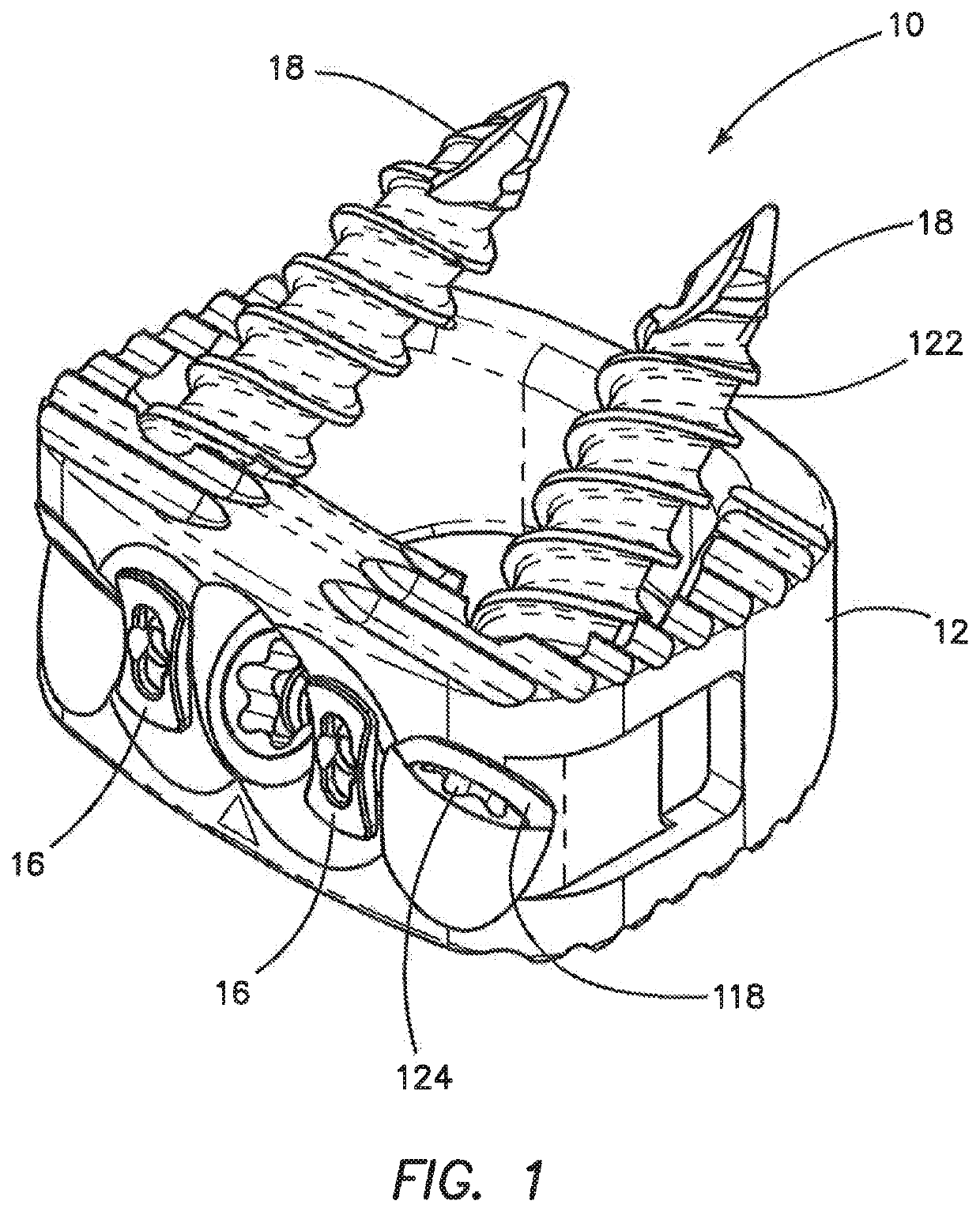
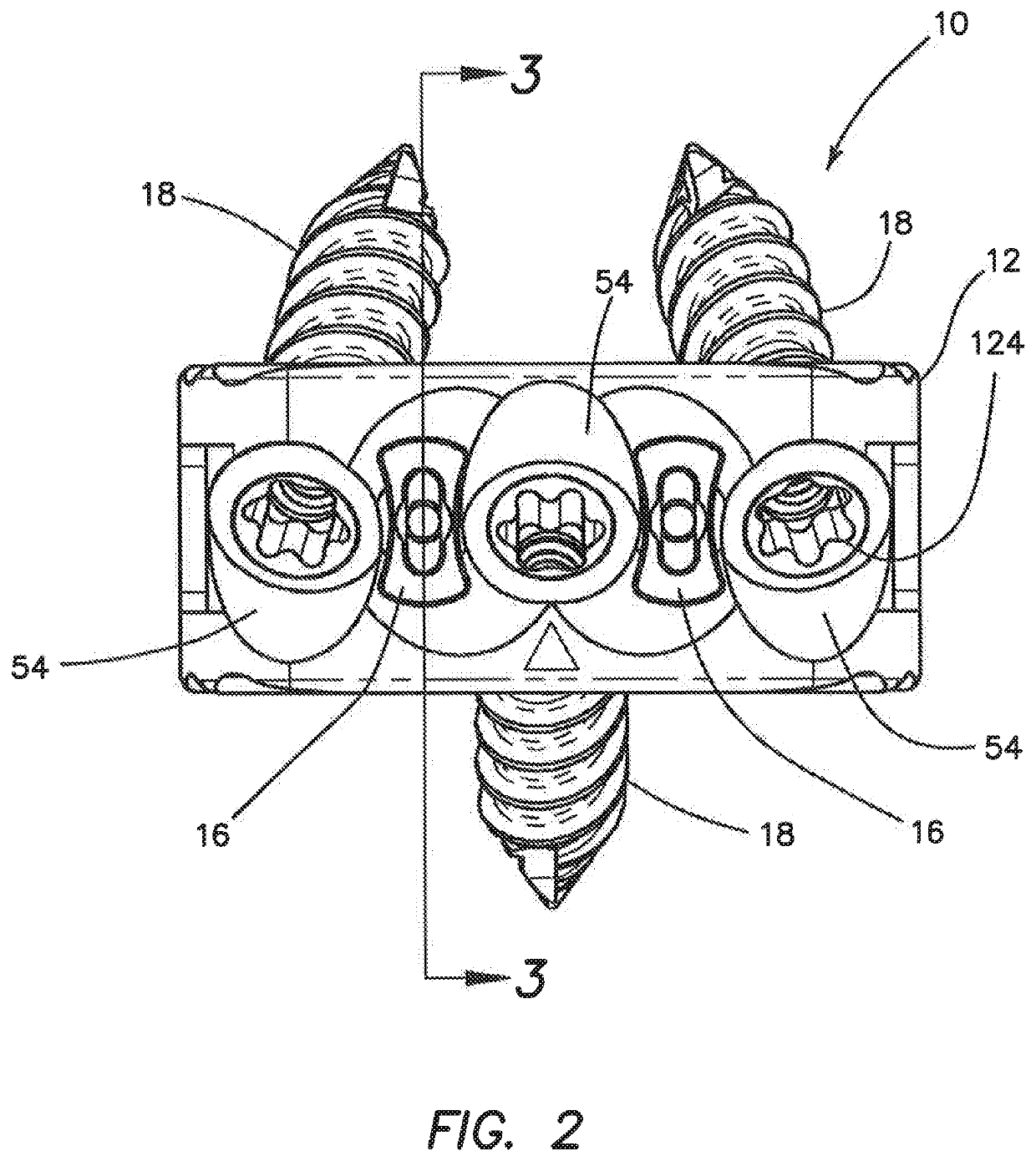
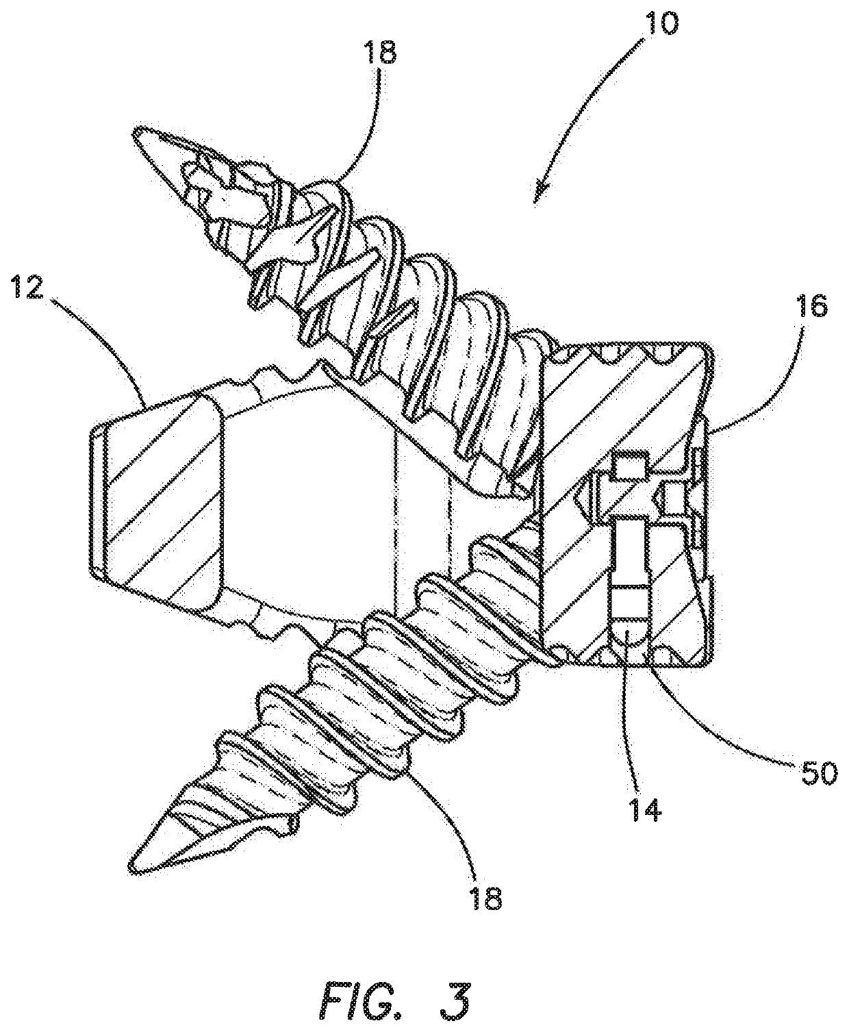
[0042]FIGS. 1-10 depict an interbody spacer 10 according to one variation of the invention that may be used to stabilize or fuse vertebral bodies in the lumbar or other region of the spine. The interbody spacer 10 comprises a cage 12, at least one lock retainer 14, at least one lock 16, and bone screws 18. The figures depict an interbody spacer 10 having three bone screws 18, two locks 16 and two lock retainers 14 that correspond to the two locks 16. The lock retainers 14 are connected to the cage 12. Each lock retainer 14 is configured to receive a portion of a lock 16 and capture the lock 16 in order to connect the lock 16 to the cage 12 in a manner that permits rotational movement of the lock 16 about its longitudinal axis relative to the cage 12. Bone screws 18 are inserted into the cage 12 and when positioned into bone, each lock 16 is rotated from an unlocked configuration in which each lock 16 does not cover the one or more bone screw 18 to a locked configuration in which eac...


PUM


Abstract

An interbody spacer for the spine is provided. The interbody spacer includes a cage and at least one bone screw configured to anchor the cage between two vertebrae of the spine. The cage includes a lock rotationally movable with respect to the cage between a locked configuration and an unlocked configuration. When in an unlocked configuration, bone screws may be inserted and removed from the cage. When in a locked configuration, the insertion and removal pathway of the bone screw is blocked by the lock, thereby, providing backout protection for the bone screws. The lock is coupled to the cage by a pronged retainer and includes a camming surface to provide for incremental rotation of the lock. The lock includes a space-saving shape providing for maximum bone screw angulation on a laterally smaller anterior platform.

Description

FIELD OF THE INVENTION[0001]This application relates generally to spinal implants, and in particular, intervertebral spacers and fusion cages.BACKGROUND OF THE INVENTION[0002]Back pain can be caused by a variety of factors including but not limited to the rupture or degeneration of one or more intervertebral discs due to degenerative disc disease, spondylolisthesis, deformative disorders, trauma, tumors and the like. In such cases, pain typically results from compression or irritation of spinal nerve roots arising from reduced spacing between adjacent vertebrae, a damaged disc and or misalignment of the spine resulting from the injury or degeneration.[0003]Common forms of treating such pain include various types of surgical procedures in which a damaged disc may be partially or totally excised. After the disc space is prepared, one or more implants are inserted between the adjacent vertebrae in an effort to restore the natural spacing and alignment between the vertebrae, so as to re...

Claims


Application Information

Patent Timeline
Patent Type & Authority Patents(United States)
IPC IPC(8): A61F2/44A61B17/80A61F2/30A61F2/46
CPCA61F2/4455A61B17/8042A61B17/8033A61F2/4611A61F2002/3082A61F2002/30481A61F2002/30528A61F2002/30593A61F2002/30787A61F2002/30904
Inventor ALTARAC, MOTIREGLOS, JOEYBARCOHANA, BABAK
Owner NEUROSTRUCTURES
Learn More