
Pipeline strainer with magnetic insert

a technology of pipeline strainer and magnetic insert, which is applied in the direction of magnetic separation, separation process, filtration separation, etc., can solve the problems of attracting fine metal particles in the pump, and affecting the performance of the pump, so as to achieve the effect of efficiently removing these fine metal particles from the fluid

Active Publication Date: 2021-04-06
METRAFLEX
View PDF23 Cites 2 Cited by
  • Summary
  • Abstract
  • Description
  • Claims
  • Application Information

AI Technical Summary

Benefits of technology

[0006]A new pipeline strainer has been invented which includes one or more magnets that are configured to be removed from the body without causing liquid within the cavity to drain from the pipeline strainer. A drywell may be used to house the magnets. The movement of withdrawing the magnets pulls metal particles along the outer surface of the drywell toward a debris drain. Thus, the present pipeline strainer provides for magnetic particles in the fluid to be collected and removed in an effective and effective manner Additionally, the present pipeline strainer collects the particles and allows for removal of the collected particles without requiring the pipeline strainer to be taken offline.
[0014]It is contemplated that the magnet is configured to be removed from the drywell without causing liquid within the cavity to drain from the pipeline strainer.

Problems solved by technology

However, while the pumps may be efficient, the magnets in the pump attract fine metal particles, such as iron oxides, that are in the water.
The fine metal particles stick to the pump elements, such as the impellers, negatively impacting the pump's performance.
The pores in conventionally used straining elements are typically too large to efficiently remove these fine metal particles from the fluid.
While presumably effective for their intended purposes, some of these pipeline strainers do not allow for the magnets to be easily removed without taking the pipeline strainer offline.
Additionally, others do not allow for the magnets to be removed in a quick and efficient manner.

Method used


Image

  • Pipeline strainer with magnetic insert

Examples


Embodiment Construction

[0023]As mentioned above, a new pipeline strainer has been invented which includes a magnet removably inserted into the body.

[0024]Accordingly, with reference the attached drawing, one or more embodiments of the present invention will now be described with the understanding that the described embodiments are merely preferred and are not intended to be limiting.

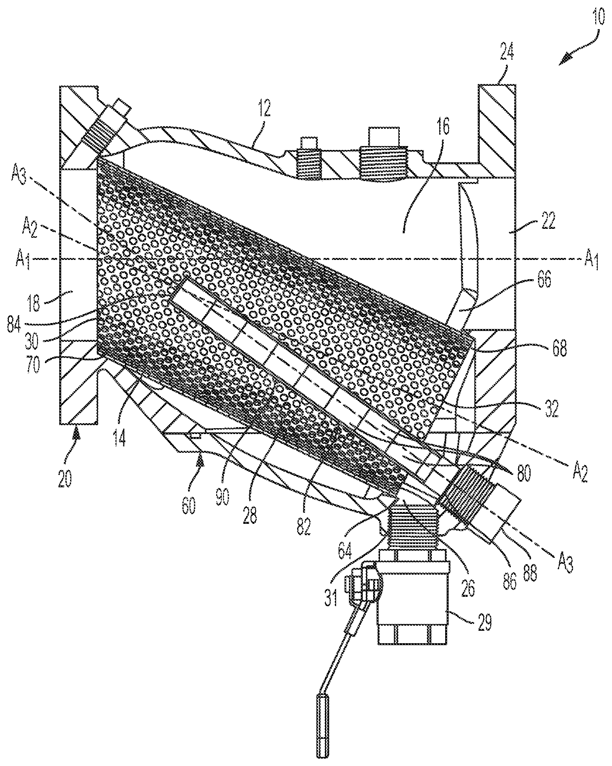
[0025]With reference to the FIGURE, a pipeline strainer 10 according to one or more embodiments of the present invention comprises a body 12. The body 12 can be made from a variety of appropriate materials, including, for example, iron, carbon steel, carbon moly, stainless steel, chrome moly, aluminum, bronze, monel, nickel, HASTELLOY® B, HASTELLOY® C, titanium, and plastic.

[0026]The pipeline strainer 10 also includes a straining element 14. Inside of the body 12 is a cavity 16 which houses the straining element 14. The body 12 includes an inlet 18 to the cavity 16 for a fluid disposed at a first end 20 of the body 12. An outl...


PUM

PropertyMeasurementUnit
angleaaaaaaaaaa
angleaaaaaaaaaa
angleaaaaaaaaaa

Abstract

A pipeline strainer having a body with a straining element therein. One or more magnets are removably inserted into the straining element and configured to be removed from the body without causing liquid within the cavity to drain from the pipeline strainer. A drywell is used to house the magnets. The movement of withdrawing the magnets pulls metal particles along the outer surface of the drywell toward a debris drain.

Description

FIELD OF THE INVENTION[0001]The present invention relates to a pipeline strainer, and more particularly to a pipeline strainer that includes a magnet for removing metal particles within a fluid passing through the pipeline strainer.BACKGROUND OF THE INVENTION[0002]Pipeline strainers are used for protecting pumps, compressors, turbines, meters, automatic valves, sprinkler heads, nozzles, steam traps, heat exchangers, meters, and other pipeline equipment. The pipeline strainer mechanically removes solids from a flowing fluid with a perforated, mesh, or wedge wire straining element. The solids are retained in the straining element, allowing the fluids to flow therethrough and be passed to downstream equipment. After a certain period of time, a drain in the pipeline strainer is opened to remove the retained debris in order to avoid excess pressure drop associated with the collection of solids in the straining element.[0003]Recently, there has been an increase in the interest and use of ...

Claims


Application Information

Patent Timeline
Patent Type & Authority Patents(United States)
IPC IPC(8): B01D35/06B01D35/02B01D35/26B01D29/31
CPCB01D35/06B01D29/31B01D35/02B01D35/26B01D2201/16B03C1/0332B03C1/284B03C1/286B03C1/288B03C1/30B03C2201/18F16L55/24
Inventor RICHTER, JAMES REYNOLDKISH, DANIEL R.TAYLOR, MICHAEL ALBERT
Owner METRAFLEX
Learn More