Device and method for manipulating an inner conductor

a technology of inner conductors and devices, applied in the field of devices and, can solve the problems of undefined separation behavior, angled inner conductors, and difficulty in subsequent allocation of inner conductors

Active Publication Date: 2021-01-26
KOMAX HOLDING
View PDF34 Cites 0 Cited by
  • Summary
  • Abstract
  • Description
  • Claims
  • Application Information

AI Technical Summary

Benefits of technology

[0008]It is an object of the present invention to provide a device or a method for manipulating an inner conductor from a plurality of inner conductors at a stripped end of a sheathed cable wherein a defined inner conductor can be manipulated or separated and reliably associated.
[0018]The manipulation device is pivotable from the initial position about a pivot axis which extends essentially perpendicular to the axial direction of the end of the sheathed cable. The end of the inner conductor follows this pivoting movement as a result of the mechanical contact through the needle. The inner conductor can thus be manipulated in such a way that its end in question is pivoted out of the axial direction in a defined manner in a defined direction. The inner conductor can thus be separated reliably.
[0019]The inner conductor gripper of the manipulation device can securely grip the thus separated inner conductor, whereupon the needle can be retracted into its initial position. It can thus be ensured that the inner conductor gripper grips a specifically determined inner conductor from the plurality of inner conductors.
[0022]The image capture device is, for example, a digital camera, which is inexpensive and readily available. Typically, the image capture device is oriented to detect an image in the plane perpendicular to the cable axis. The control device and the alignment device can be configured as separate controls or also as an integrated control. For example, the control device and / or the alignment device is configured as a standard computer, as an industrial computer, as an integrated circuit or the like.

Problems solved by technology

However, the separating behavior is undefined in the conventional method.
Therefore, the conventional method results in the disadvantage that the inner conductors which are angled after the use of the air nozzle are undefined in the space.
This makes a subsequent allocation of the inner conductors more difficult, for example, in order to transfer these individually and in a defined sequence into a suitable fastening device.

Method used


Image

  • Device and method for manipulating an inner conductor
  • Device and method for manipulating an inner conductor
  • Device and method for manipulating an inner conductor

Examples


Embodiment Construction

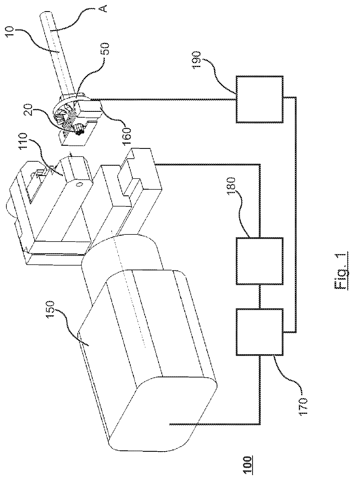
[0046]FIG. 1 shows a perspective schematic view of a device 100 for manipulating an inner conductor 20 from a plurality of inner conductors 20 on a stripped end of a sheathed cable 10 according to an embodiment of the invention. Insofar as the explanation does not depend on a distinction of the individual inner conductors in the bundle of inner conductors, an inner conductor is provided with the reference symbol 20. The sheathed cable 10 extends essentially linearly along a cable axis which defines an axial direction A. Each inner conductor 20 on the stripped end of the sheathed cable 10 also extends in a straight line along an inner conductor axis and parallel to the cable axis in FIG. 1, which shows the state before a manipulation operation of the inner conductor 20.

[0047]The sheathed cable has an end, on which the outer insulation—the sheath—of the sheathed cable 10 is removed and the inner conductors 20 are exposed. Each inner conductor 20 is formed from a twisted strand bundle ...


PUM


Abstract

A device and a method manipulate an inner conductor from several inner conductors at a stripped end of a sheathed cable. The device includes a manipulation device pivotable from an initial position about a pivot axis extending perpendicular to the axial direction of the cable end alignable relative to the manipulation device in a plane extending perpendicular to the cable end axis. The manipulation device includes a needle movable towards an inner conductor end in the initial position along a needle axis; and an inner conductor gripper gripping the inner conductor end. The method includes aligning the cable end relative to the manipulation device to align the needle axis with the inner conductor axis; moving the needle towards the inner conductor end, and establishing needle and inner conductor end contact; pivoting the manipulation device about the pivot axis; and gripping the inner conductor end by the inner conductor gripper.

Description

CROSS REFERENCE TO RELATED APPLICATIONS[0001]Applicant claims priority under 35 U.S.C. § 119 of European Application No. 16206365.5 filed Dec. 22, 2016, the disclosure of which is incorporated by reference.BACKGROUND OF THE INVENTION1. Field of the Invention[0002]The invention relates to a device and a method for manipulating an inner conductor from a plurality of inner conductors at a stripped end of a sheathed cable.2. Description of the Related Art[0003]Electrical sheathed cables have a bundle of inner conductors, wherein the inner conductor bundle is surrounded overall by an electrically insulating material, the so-called sheath. The sheath forms an outer insulation layer. Each of the inner conductors is formed from individual strands which in turn are each surrounded by an electrically insulating material, typically a plastic insulation, as an inner insulation layer. The strands are, for example, twisted strands of copper or of aluminum.[0004]Sheathed cables are often processed...

Claims


Application Information

Patent Timeline
Patent Type & Authority Patents(United States)
IPC IPC(8): H01R43/28H01R43/20H02G1/14
CPCH02G1/14H01R43/28H02G1/12
Inventor WICKI, BEAT
Owner KOMAX HOLDING
Why Eureka
Try Eureka