
Locking device and method for locking a wheel track to an end beam, carton flow bed rack and use

a locking device and end beam technology, applied in storage devices, mechanical conveyors, conveyors, etc., can solve the problems of deformation of the wheel track and/or the end beam to which it is connected, the wheel track may not be secured and fixed to the end beam, and the deformation of the wheel track and/or the end beam, etc., to achieve convenient installation and removal, sufficient stability and support, and easy mounting and/or assembly

Active Publication Date: 2020-10-06
INTERROLL HLDG
View PDF8 Cites 0 Cited by
  • Summary
  • Abstract
  • Description
  • Claims
  • Application Information

AI Technical Summary

Benefits of technology

[0010]The locking device is configured and suitable for connecting the wheel track to the end beam, because the locking device may provide a substantial durability, strength, and / or stability. Furthermore, the locking device may enable a simple and quick installation.
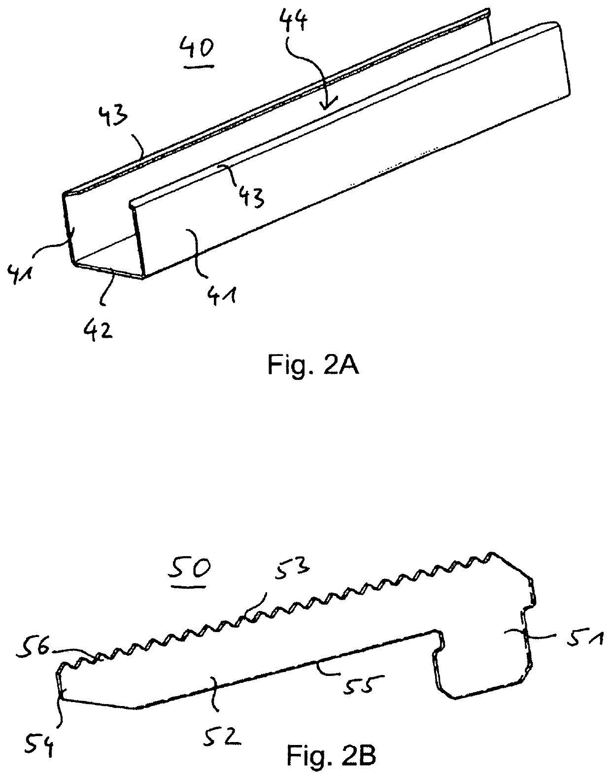
[0044]According to an embodiment, some wheel axles of the wheels of the wheel track are arranged between pointed teeth along an upper rim of the protrusion of the locking plate. This enables a safe and predetermined positioning of the locking device provided by the locking plate and the cover rail with respect to the wheel track.

Problems solved by technology

In particular, the provision of carton flow bed racks comprising wide levels may result in a deformation of the wheel tracks and / or the end beams they are connected to.
A deformation may also result from the weight of the loads being transported along the wheel tracks.
The problem relates to preventing the deformation of wheel tracks and / or end beams of carton flow bed racks, in particular providing an improved connection of the wheel tracks with the end beams of a rack, more particularly of a carton flow bed rack that requires sufficient stability.
While this may provide sufficient support for carrying the loads and / or the weight of the wheel tracks, the wheel track may not be secured and fixed to the end beam by this construction alone.
Furthermore, this construction alone may result in a deformation of the wheel tracks and / or end beams.

Method used


Image

  • Locking device and method for locking a wheel track to an end beam, carton flow bed rack and use
  • Locking device and method for locking a wheel track to an end beam, carton flow bed rack and use
  • Locking device and method for locking a wheel track to an end beam, carton flow bed rack and use

Examples


Embodiment Construction

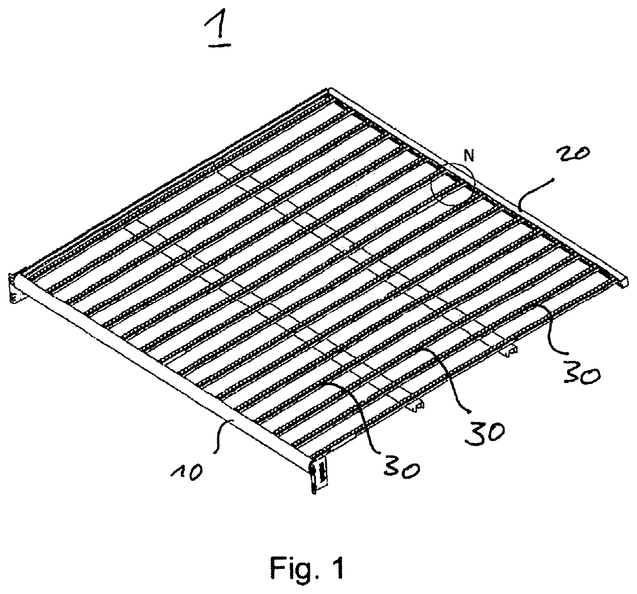
[0057]FIG. 1 shows a perspective view of a carton flow bed rack level 1. A carton flow bed rack may comprise a plurality of such levels 1. The level 1 comprises a plurality of wheel tracks 30 aligned substantially parallel to each other along the level 1 of the carton flow bed rack. Each wheel track 30 is mounted at a first end to a load beam 20 and at a second, opposite end to an unload beam 10. The unload beam 10 and the load beam 20 are provided as end beams of the carton flow bed rack.

[0058]Another carton flow bed rack level may comprise an end beam at a first side that is both a load beam and an unload beam and, at the opposite side, a stop beam as an end beam where loads are neither unloaded nor loaded to the level.

[0059]Each wheel track comprises a plurality of wheels. Upper ends of wheel mantels of the wheels form a conveying surface for the loads along the carton flow bed rack level 1. The loads may be conveyed along the extension direction of the wheel tracks 30. Each load...


PUM


Abstract

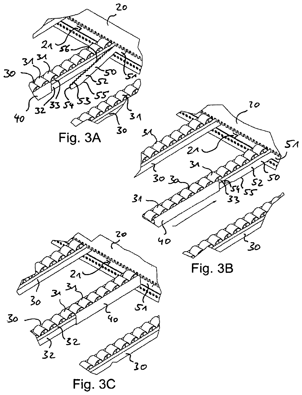
A locking device for locking a wheel track (30) of a carton flow bed rack to an end beam (10; 20) of the carton flow bed rack in a mounting position includes a locking plate (50) for connecting the wheel track (30) to the end beam (10; 20) and a cover rail (40) for fixing the locking plate (50) to the wheel track (30). The locking plate (50) has a mounting end (51) configured to engage the end beam (10; 20) in the mounting position. The locking plate (50) further has an elongated protrusion (52) configured to protrude out of the end beam (10; 20) in the mounting position. The cover rail (40) is configured to encase at least partially both the protrusion (52) of the locking plate (50) and an end section of the wheel track (30) in the mounting position.

Description

BACKGROUNDField of the Invention[0001]The invention relates to a locking device and a method for locking a wheel track of a carton flow bed rack to an end beam of the carton flow bed rack, a carton flow bed rack, and a use of a locking device.Related Art[0002]Carton flow bed racks are used to store and / or distribute loads, in particular parcels, cartons, and / or other goods. Carton flow bed racks are characterized in that they comprise a load side from which the rack is loaded and an unload side from which the rack is unloaded. There are carton flow bed racks that are loaded and unloaded at the same side, and others that are loaded and unloaded at different, e.g. opposite, sides. Carton flow bed racks may comprise wheel tracks to transport loads between a first end beam at a first side of the rack and a second end beam at a second, opposite side of the rack.[0003]For enabling a stable support of these wheel tracks and the loads, the wheel tracks are mounted to the horizontally aligne...

Claims


Application Information

Patent Timeline
Patent Type & Authority Patents(United States)
IPC IPC(8): B65G1/02B65G13/11
CPCB65G1/023B65G13/11B65G35/00
Inventor LAPLACE, JEAN MICHEL
Owner INTERROLL HLDG
Learn More