Clamshell electronic device
a technology of electronic devices and shells, applied in the field of shell electronic devices, can solve the problem that users cannot obtain information from the display
- Summary
- Abstract
- Description
- Claims
- Application Information
AI Technical Summary
Benefits of technology
Problems solved by technology
Method used
Image
Examples
first embodiment
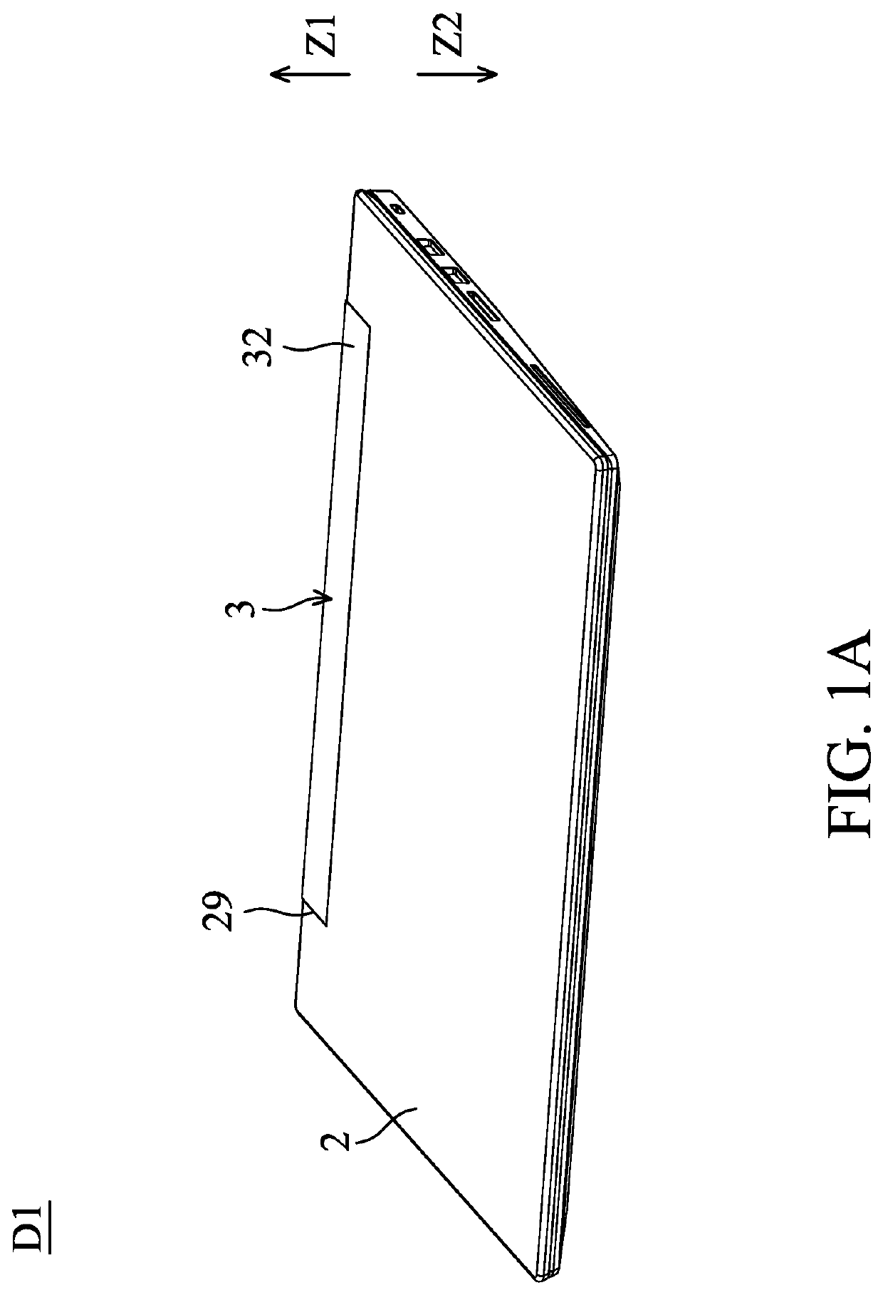
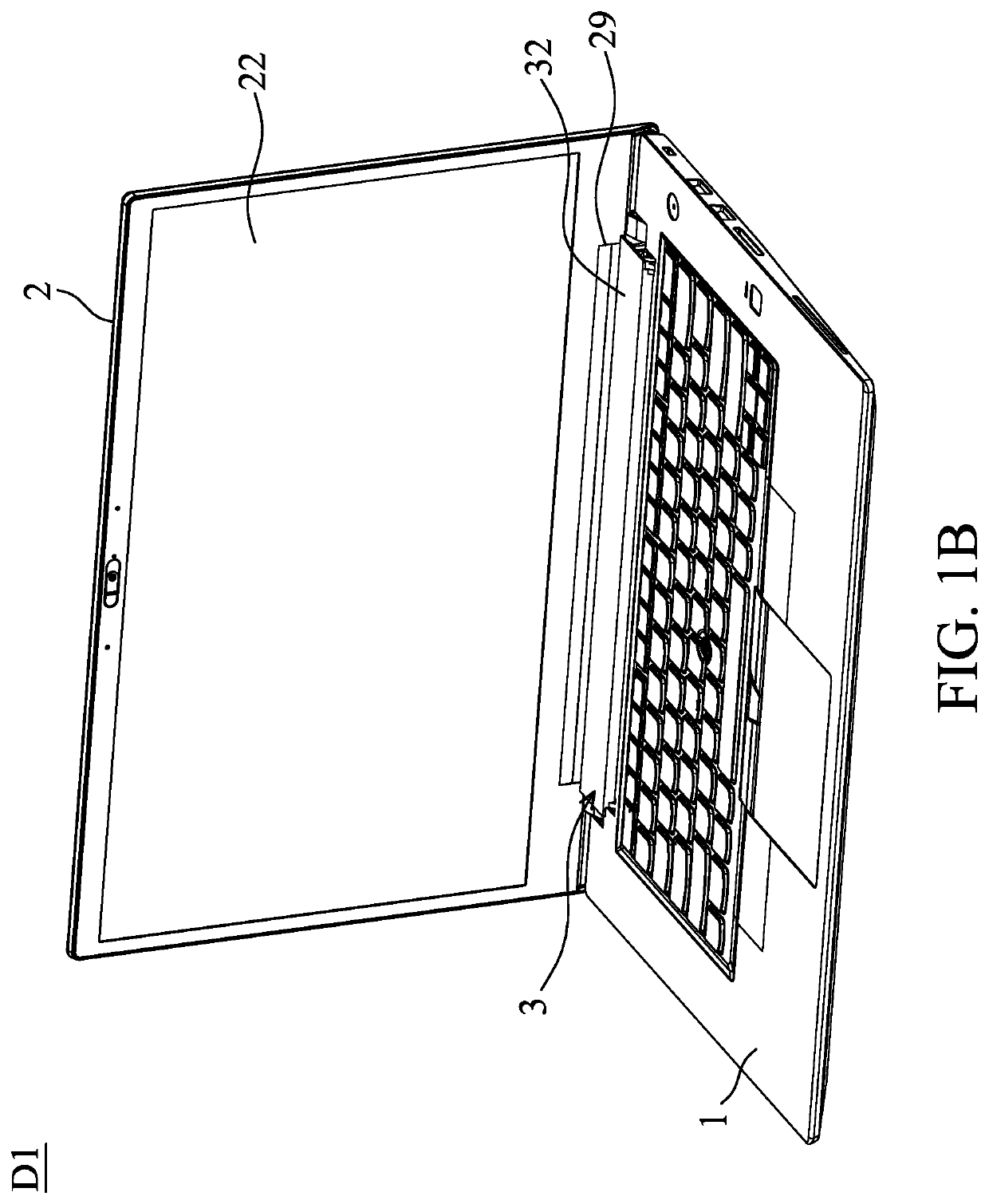
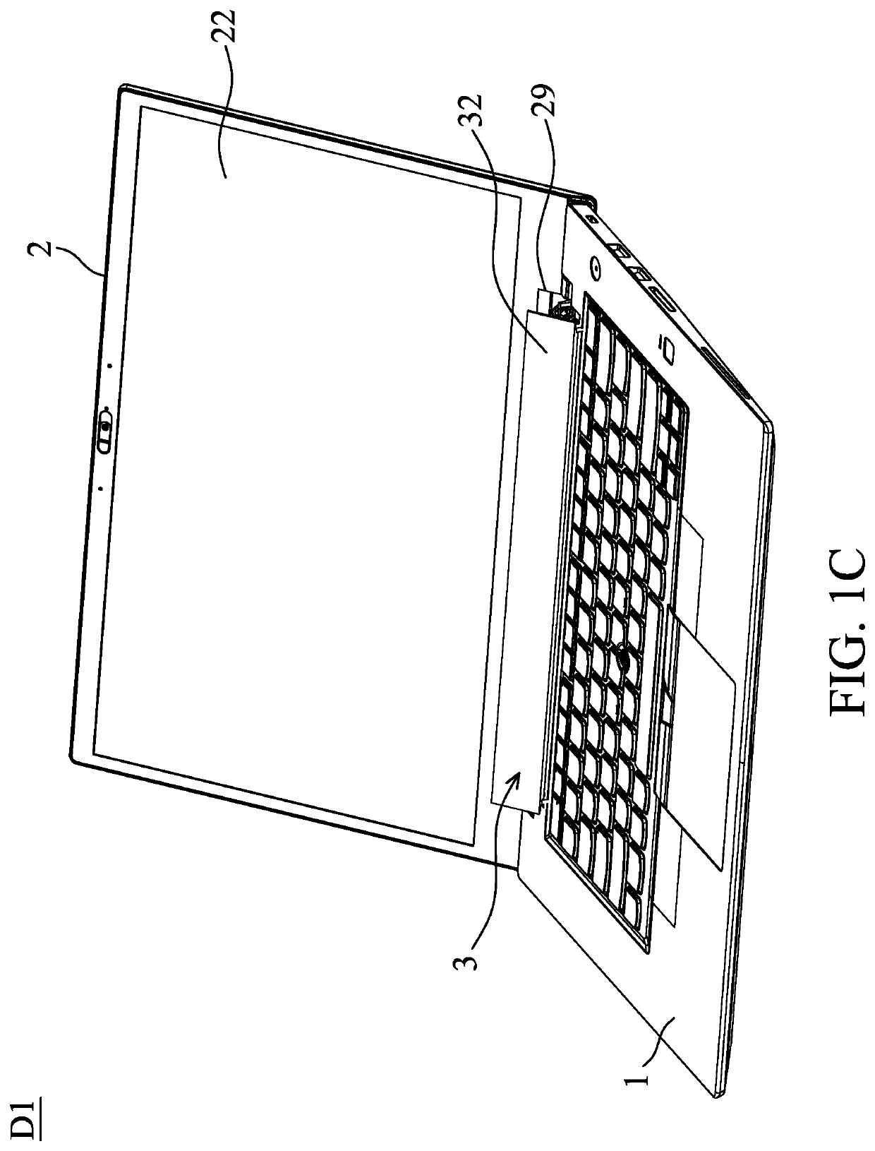
[0028]FIGS. 1A, 1B and 1C show a clamshell electronic device D1 of the invention. The clamshell electronic device D1 includes a device body 1, a cover 2, an auxiliary display unit 3 and an orientation adjustment mechanism 401 (not shown). The cover 2 pivots on the device body 1, and the cover 2 includes a cover notch 29. The auxiliary display unit 3 is disposed on the device body 1. The auxiliary display unit 3 is adapted to be rotated between a first unit orientation (FIGS. 1A and 1B) and a second unit orientation (FIG. 1C). Particularly, in one embodiment, the auxiliary display unit 3 pivots on the device body 1. The orientation adjustment mechanism 401 (not shown) is connected to the cover 2 and the auxiliary display unit 3. When the cover 2 is in a first cover orientation (FIG. 1A) relative to the device body 1, the cover 2 covers the device body 1, and the auxiliary display unit 3 is in the first unit orientation and corresponds to the cover notch 29. While the cover 2 is being...
second embodiment
[0036]FIGS. 3A, 3B and 3C show an orientation adjustment mechanism 402 of the invention. With reference to FIGS. 3A, 3B and 3C, in this embodiment, the orientation adjustment mechanism 402 includes a pushing rod 421. The device body 1 includes a shaft 11. The pushing rod 421 pivots on the shaft 11. The pushing rod 421 includes a pushing rod connection end 422 and a pushing rod abutting end 423. The pushing rod connection end 422 is affixed to the cover 2, and the pushing rod abutting end 423 is adapted to push the auxiliary display unit 3.
[0037]With reference to FIGS. 3A, 3B and 3C, in this embodiment, the auxiliary display unit 3 includes a unit surface 39. While the cover 2 is being rotated relative to the device body 1 from the first cover orientation (FIG. 3A) to the third cover orientation (FIG. 3B), the pushing rod abutting end 423 is separated from the unit surface 39, and the auxiliary display unit 3 is therefore not pushed by the pushing rod abutting end 423. While the cove...
third embodiment
[0038]FIGS. 4A, 4B and 4C show the orientation adjustment mechanism 403 of the invention. With reference to FIGS. 4A, 4B and 4C, in one embodiment, the orientation adjustment mechanism 403 includes a first push member 431 and a second push member 432. The device body 1 includes a shaft 11. The first push member 431 pivots on the shaft 11. The first push member 431 includes a push member connection end 433 and a first push portion 434. The push member connection end 433 is connected to the cover 2. The second push member 432 includes a push member abutting end 435 and a second push portion 436. The push member abutting end 435 abuts the auxiliary display unit 3. The first push portion 434 is adapted to push the second push portion 436 and rotate the second push member 432. In this embodiment, the first push member 431 and the second push member 432 are rotated around an axis of the shaft 11.
[0039]With reference to FIGS. 4A, 4B and 4C, in one embodiment, while the cover 2 is being rot...
PUM
 Abstract
Description
Claims
Application Information
 - R&D
- Intellectual Property
- Life Sciences
- Materials
- Tech Scout
- Unparalleled Data Quality
- Higher Quality Content
- 60% Fewer Hallucinations
Browse by: Latest US Patents, China's latest patents, Technical Efficacy Thesaurus, Application Domain, Technology Topic, Popular Technical Reports.
© 2025 PatSnap. All rights reserved.Legal|Privacy policy|Modern Slavery Act Transparency Statement|Sitemap|About US| Contact US: help@patsnap.com


