Method for controlling a gear shift in a transmission arrangement

a transmission arrangement and gear shift technology, applied in the direction of gearing control, road vehicle drive control system, toothed gearing, etc., can solve the problems of not being able to disengage, work machine is frequently operated, and prone to lower drag losses, so as to achieve the effect of lowering drag losses

Active Publication Date: 2020-09-22
VOLVO CONSTR EQUIP AB
View PDF11 Cites 0 Cited by
  • Summary
  • Abstract
  • Description
  • Claims
  • Application Information

AI Technical Summary

Benefits of technology

[0013]An advantage of the present invention is that the above method enables for the second locking mechanism to be designed as a so-called dog clutch. Thus, according to an example embodiment, the second locking mechanism may be a dog clutch. A dog clutch is advantageous to use since it does not use friction to connect the planet carrier of the second planetary gear set to the transmission housing. Rather, a dog clutch uses interference between connecting parts. Hence, the second locking mechanism is more durable in comparison to e.g. a friction brake. Also, lower drag losses occur when the locking mechanism is disengaged.
[0014]According to an example embodiment of the present invention, the method may comprise the step of positioning the first locking mechanism in a disengaged state when the second locking mechanism has been positioned in the engaged state.
[0015]Hereby, when the engagement process of the second locking mechanism is ended, the first locking mechanism can be positioned in the disengaged state, thus completing the gear change process.
[0016]According to an example embodiment of the present invention, the transmission arrangement may comprise a third locking mechanism for selectively locking the sun gear of the first planetary gear set and the sun gear of the second planetary gear set to the transmission housing; and a second connecting mechanism for selectively connecting the sun gear of the third planetary gear set to the planet carrier of the second planetary gear set and to the ring gear of the first planetary gear set. Accordingly, also components of the first planetary gear set may be selectively connectable to the transmission housing.
[0017]According to an example embodiment of the present invention, the method may comprise the step of positioning the third locking mechanism in a disengaged state when reducing the speed of the planet carrier of the second planetary gear set.
[0018]Hereby, the sun gear of the first planetary gear set will not be fixated to the transmission housing and the output shaft will not be in mechanical connection with the planet carrier of the second planetary gear set which will enable the output shaft to continuously rotate when the second locking mechanism is positioned in the engaged state.

Problems solved by technology

Thus, the working machine is frequently operated with large and heavy loads in rough terrain and on slippery ground where no regular roads are present.
Hence, no connecting mechanism or the like is arranged between the components that are operatively connected to each other and they can therefore not be disengaged from one another during operation.
Also, lower drag losses occur when the locking mechanism is disengaged.

Method used


Image

  • Method for controlling a gear shift in a transmission arrangement
  • Method for controlling a gear shift in a transmission arrangement
  • Method for controlling a gear shift in a transmission arrangement

Examples


Embodiment Construction

[0065]The present invention will now be described more fully hereinafter with reference to the accompanying drawings, in which exemplary embodiments of the invention are shown. The invention may, however, be embodied in many different forms and should not be construed as limited to the embodiments set forth herein; rather, these embodiments are provided for thoroughness and completeness. Like reference character refer to like elements throughout the description.

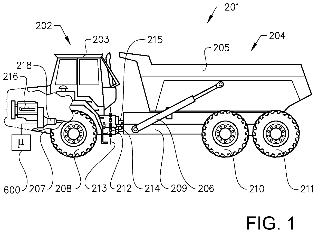
[0066]FIG. 1 is a side view of a working machine 201 in the form of an articulated hauler having a tractor unit 202 with a cab 203 for a driver and a trailer unit 204 with a platform having a dump body 205, here in the form of a container, arranged thereon, for receiving load. The dump body 205 is preferably pivotally connected to the rear section and tiltable by means of a pair of tilting cylinders 206, for example hydraulic cylinders. The tractor unit 202 has a frame 207 and a pair of wheels 208 suspended from the frame 207...


PUM


Abstract

A method is provided for controlling a gear shift from a forward gear to a reverse gear in a transmission arrangement, the method including the steps of: positioning a first locking mechanism and a first connecting mechanism at least in a partially engaged state for reducing a rotational speed of a planet carrier of a second planetary gear set; and positioning a second locking mechanism in an engaged state when a rotational speed of the planet carrier of the second planetary gear set is below a predetermined threshold limit.

Description

BACKGROUND AND SUMMARY[0001]The present invention relates to a method for controlling a gear shift in a transmission arrangement. The invention also relates to a control unit for controlling the gear shift and a vehicle comprising such a transmission arrangement and control unit. The invention is applicable on vehicles, in particularly working machines such as e.g. wheel loaders, articulated haulers, dump trucks, etc. Although the invention will mainly be described in relation to an articulated hauler, it may also be applicable for other type of vehicles such as e.g. trucks.[0002]In connection with transportation of heavy loads at construction sites or the like, a working machine is often used. The working machines may be utilized for transportations in connection with road or tunnel building, sand pits, mines, forestry and similar environments. Thus, the working machine is frequently operated with large and heavy loads in rough terrain and on slippery ground where no regular roads ...

Claims


Application Information

Patent Timeline
Patent Type & Authority Patents(United States)
IPC IPC(8): F16H61/04F16H3/66F16H61/02F16H3/44
CPCF16H61/0437F16H3/66F16H61/0204F16H2200/0065B60Y2200/417F16H2200/2064F16H2200/2094F16H2200/0091F16H2200/2048F16H2200/2046B60Y2300/18041F16H2312/09F16H2003/445F16H2200/0095F16H2200/2012F16H2061/0481
Inventor DERSJÖ, JANMATTSSON, PERARNE, JOHNNY
Owner VOLVO CONSTR EQUIP AB
Why Eureka
Try Eureka