
Automatic detection of teeth clenching and/or teeth grinding

a technology of automatic detection and teeth clenching, applied in the field of automatic detection of teeth clenching and/or teeth grinding, can solve the problems of tooth wear, serious dental damage, damage or unwanted effects, etc., and achieve the effect of avoiding calibration and being convenient to us

Active Publication Date: 2020-08-11
SUNSTAR SUISSE SA
View PDF35 Cites 5 Cited by
  • Summary
  • Abstract
  • Description
  • Claims
  • Application Information

AI Technical Summary

Benefits of technology

[0011]In order to solve the above described problems and address the above described needs, the present disclosure relates to a user-friendly device which automatically detects teeth clenching and / or teeth grinding without the use of a manual set up. The user friendly device may be easy to use in terms of daily setup, such that particularly calibration is avoided. Accordingly, the present disclosure relates to a user-friendly method which automatically set up a device such that it becomes adapted to the individuals, in particular such that the device detects the teeth clenching and teeth grinding signal and distinguish them from other signals as given off by the individuals.

Problems solved by technology

Teeth clenching and / or teeth grinding may be done more or less consciously or even completely unaware, for example in the sleep, and may also cause damage or unwanted effects.
This affliction may cause serious dental damages such as for example wearing of the teeth, damages to lips and the tongue, lose teeth, gingival pockets etc.
Day-time bruxism may be perceived as a bad habit.
However, events related to bruxism may be difficult to detect because they may be similar to event related to ordinary teeth clenching.
A manual set up is far from optimal in that the sensing device may then depend on the person setting up the device.
If the detected signals may be used, as for example by providing a treatment stimulus to the patient, an incorrect set up may be problematic in that a correct treatment may not be provided.

Method used


Image

  • Automatic detection of teeth clenching and/or teeth grinding
  • Automatic detection of teeth clenching and/or teeth grinding
  • Automatic detection of teeth clenching and/or teeth grinding

Examples


example 1

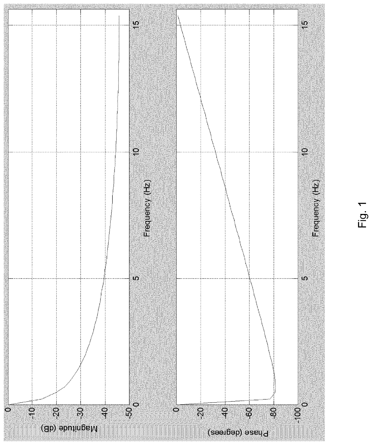
[0100]In order to calculate a background level, the background level may be a low pass filtered EMG signal envelope as here described.

[0101]The filter is a 1st-order autoregressive filter in the form:

y(n)=0.99·y(n−1)+0.01·x(n−80), where

[0102]x(n−80) is the 2.56 second old envelope value (80 samples / 31.25 samples / s=2.56 s),

[0103]y(n−1) is the latest value of the background level,

[0104]y(n) is the new value of the background level,

[0105]0.99 is the filter coefficient,

[0106]0.01 is a gain-factor on the input signal, to ensure an overall gain of 1.

[0107]The calculation is implemented in integer arithmetic, to reduce computational load in the embedded processor. This is done by multiplying the values from the FFT algorithm (which is an 8-bit algorithm), with a scaling factor of 10000. Further, the filter described above is calculated as

y(n)=(99·y(n−1)+1·x(n−80)) / 100

[0108]as decimal numbers cannot be represented in integer arithmetic.

[0109]The Magnitude and Phase responses of the filter a...

example 2

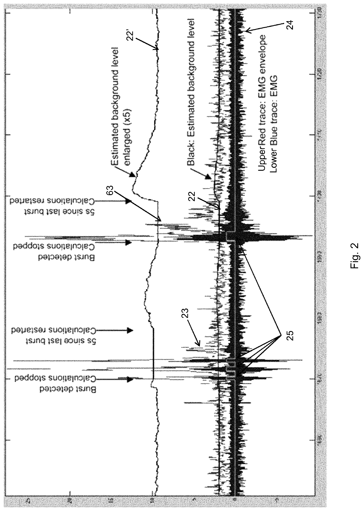
[0110]An illustration of an embodiment of the method for automatic detection of teeth clenching is shown in FIG. 2. In FIG. 2, the data is EMG data obtained from EMG signals. The signal envelope 23 is calculated by FFT of the raw EMG signal 24. As can be seen from FIG. 2, the estimated background level 22, 22′ is constantly changing with respect to time, except for the periods wherein the calculation is stopped, i.e. wherein the method is fixing the threshold level, and after which the calculations are restarted. It can be seen in FIG. 2 that four bursts 25 are detected in total.

example 3

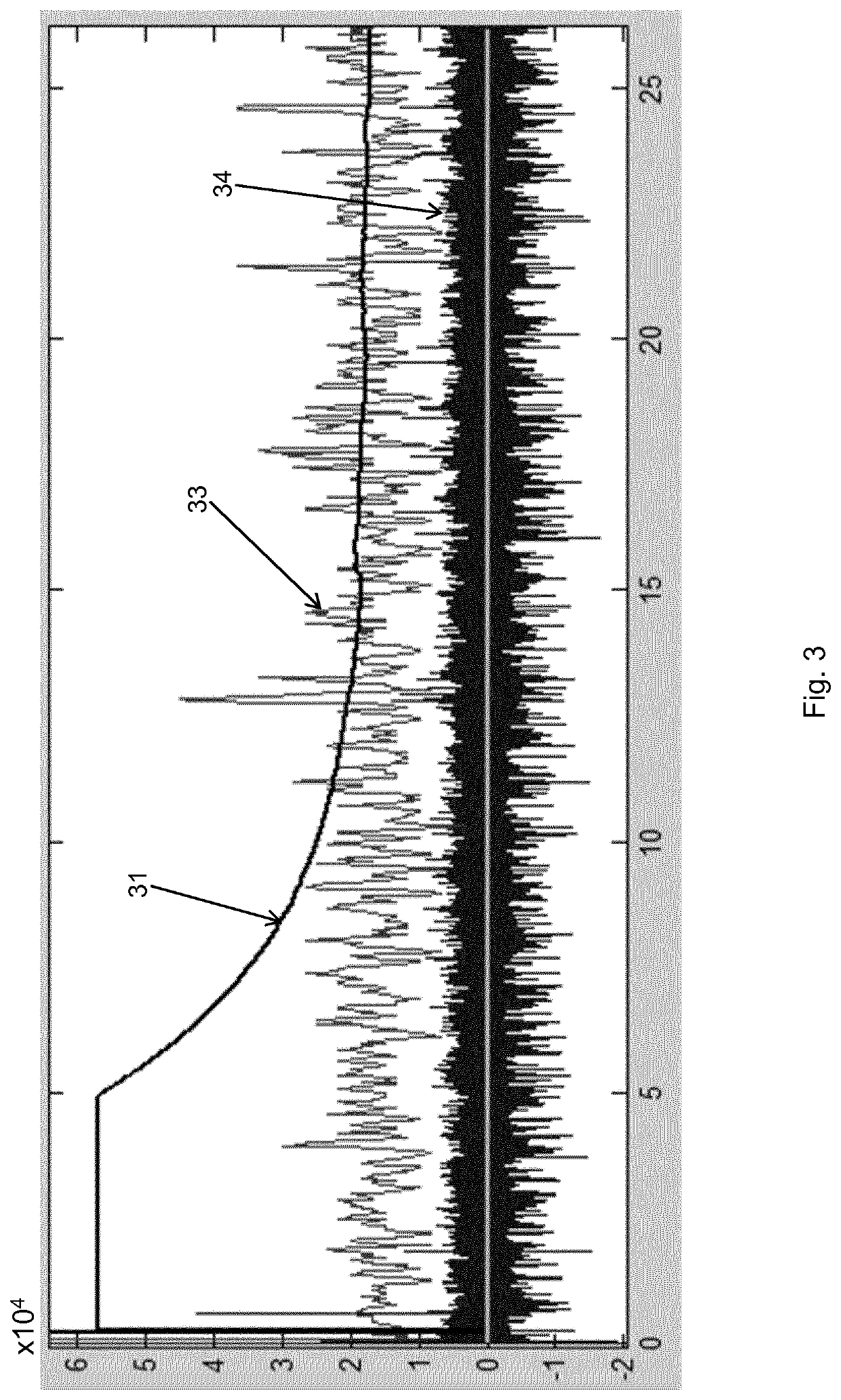
[0111]An illustration of another embodiment of the method for automatic detection of teeth clenching is shown in FIG. 3. In FIG. 3, the data is EMG data obtained from EMG signals. In FIG. 3 is shown the initial output from the method when no activity related to the teeth clenching has been assigned. The raw EMG signal 34 is sampled at 2000 Hz. The signal envelope 33 is calculated by a 64-point FFT and averaging pins 7-13, as this corresponds to an RMS value of frequencies between 218 and 406 Hz. As can be seen from FIG. 3 the initial output of the background level 31 is rather high and the method waits 5 seconds before it starts calculating new outputs (assuming that a signal may have been present before the start of the method). The initial value of the background level 31 is set to a higher value than expected in the recorded signal 34. Due to the high start level and depending on the actual level of background activity, it can take up to 10 s for the filter to find the precise le...


PUM


Abstract

The present disclosure provides a computer implemented method for automatic detection of teeth clenching and / or teeth grinding in a dataset representing the level of biting force vs. time of a subject, the method comprising the steps of a) calculating a threshold level of biting force assigned to time t=t1 based on a background level determined from the dataset at a prior time t=t1−Tback, where Ttrack is a first predefined period of time, b) checking the level of biting, and if the level of biting force at time, t, exceeds the threshold level assigned to time t for a second predefined period of time, Tclench / grind, then assigning an event of teeth clenching to time t, c) if an event of teeth clenching has been assigned to time t, then either waiting a predefined period of time 10 Twait, or waiting until the level of biting is below the threshold for another predefined period of time Tend, d) if no events of teeth clenching and / or teeth grinding have been assigned for a third predefined period of time Tsilence, then repeating steps a)-c), e) if events of teeth clenching and / or teeth grinding have been assigned for a third predefined period of time Tsilence, then repeating only steps b)-c).

Description

FIELD OF INVENTION[0001]The present disclosure relates to automatic detection of a predefined event in a dataset, more specifically to a method, a device and a system for automatic detection of teeth clenching and / or teeth grinding.BACKGROUND OF INVENTION[0002]In a number of circumstances it is desirable to detect teeth clenching and / or teeth grinding of especially human beings, in particular with the objective of being able to detect and possibly avoid undesirable, unnecessary and / or potentially harmful teeth clenching and / or grinding. In particular it is desirable to be able to detect such teeth clenching and / grinding with the objective of being able to interfere in such a manner that the undesirable activity may be limited or even brought to an end.[0003]Teeth clenching and / or teeth grinding may be done more or less consciously or even completely unaware, for example in the sleep, and may also cause damage or unwanted effects.[0004]Both teeth clenching and teeth grinding may be c...

Claims


Application Information

Patent Timeline
Patent Type & Authority Patents(United States)
IPC IPC(8): A61B5/00A61B5/1495A61B5/22A61B5/0488A61B5/0476A61B7/00A61B5/11A61F5/56
CPCA61B5/11A61B5/0476A61B5/486A61B5/0488A61B5/7257A61B5/228A61B5/4519A61B5/7264A61B5/1495A61B5/726A61B5/7235A61B5/4557A61B7/006A61F2005/563A61B2562/0219A61B2560/0223A61B2562/0261A61B5/389G16H50/20A61B5/369
Inventor HAUGLAND, MORTENCHRISTIANSEN, CHRISTIANTAKANO, NAO
Owner SUNSTAR SUISSE SA
Learn More