
Physiological monitoring devices, systems, and methods

Active Publication Date: 2020-06-23
MASIMO CORP
View PDF1264 Cites 12 Cited by
  • Summary
  • Abstract
  • Description
  • Claims
  • Application Information

AI Technical Summary

Benefits of technology

The patent describes a system and method for non-invasively measuring various blood constituents and analytes, such as oxygen, carboxyhemoglobin, methemoglobin, total hemoglobin, glucose, proteins, lipids, and others. The system includes an emitter that emits light, a diffuser that spreads the light over a larger tissue area, and a concentrator that collects and concentrates the spread light. The collected light is then detected by a detector and processed to determine the desired parameter. The system can be used for measuring blood flow, hydration, and other physiological characteristics. The method involves emitting light, spreading it with a diffuser, and receiving it after attenuation by the tissue measurement site. The light is then concentrated and detected by a detector. The detected light is transmitted to a processor, which determines the physiological parameter of interest. The system and method can provide non-invasive and accurate measurements of blood constituents and analytes.

Problems solved by technology

The technical problem addressed in this patent is the measurement of physiological parameters, particularly oxygen saturation, using pulse oximetry systems. The problem is that these systems are subject to various sources of measurement error, including electronic components, chemical and structural physiological differences between patients, and the effect of multiple scattering of photons.

Method used


Image

  • Physiological monitoring devices, systems, and methods
  • Physiological monitoring devices, systems, and methods
  • Physiological monitoring devices, systems, and methods

Examples


Embodiment Construction

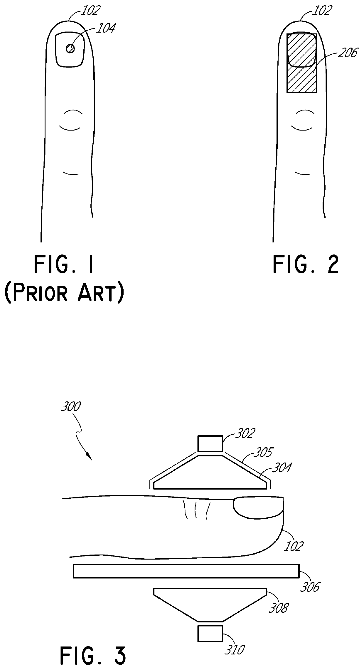
[0032]FIG. 1 illustrates schematically a conventional pulse oximetry sensor having a two-dimensional (2D) approach to pulse oximetry. As illustrated, the emitter 104 is configured to emit optical radiation as a point optical source, i.e., an optical radiation source that has negligible dimensions such that it may be considered as a point. This approach is referred to herein as “two-dimensional” pulse oximetry because it applies a two-dimensional analytical model to the three-dimensional space of the tissue measurement site 102 of the patient. Point optical sources feature a defined, freely selectable, and homogeneous light beam area. Light beams emitted from LED point sources often exhibit a strong focus which can produce a usually sharply-defined and evenly-lit illuminated spot often with high intensity dynamics. Illustratively, when looking at the surface of the tissue measurement site 102 (or “sample tissue”), which in this example is a finger, a small point-like surface area of ...


PUM


Abstract

A non-invasive, optical-based physiological monitoring system is disclosed. One embodiment includes an emitter configured to emit light. A diffuser is configured to receive and spread the emitted light, and to emit the spread light at a tissue measurement site. The system further includes a concentrator configured to receive the spread light after it has been attenuated by or reflected from the tissue measurement site. The concentrator is also configured to collect and concentrate the received light and to emit the concentrated light to a detector. The detector is configured to detect the concentrated light and to transmit a signal representative of the detected light. A processor is configured to receive the transmitted signal and to determine a physiological parameter, such as, for example, arterial oxygen saturation, in the tissue measurement site.

Description

INCORPORATION BY REFERENCE TO ANY PRIORITY APPLICATIONS[0001]The present application is a continuation of U.S. patent application Ser. No. 16 / 791,963, filed Feb. 14, 2020, which is a continuation of U.S. patent application Ser. No. 16 / 532,065 filed Aug. 5, 2019, which is a continuation of U.S. patent application Ser. No. 16 / 226,249 filed Dec. 19, 2018, which is a continuation of U.S. patent application Ser. No. 15 / 195,199 filed Jun. 28, 2016, which claims priority benefit under 35 U.S.C. § 119(e) from U.S. Provisional Application No. 62 / 188,430, filed Jul. 2, 2015, which is incorporated by reference herein. Any and all applications for which a foreign or domestic priority claim is identified in the Application Data Sheet as filed with the present application are hereby incorporated by reference under 37 CFR 1.57.FIELD OF THE DISCLOSURE[0002]The present disclosure relates to the field of non-invasive optical-based physiological monitoring sensors, and more particularly to systems, de...

Claims


Application Information

Patent Timeline
Patent Type & Authority Patents(United States)
IPC IPC(8): A61B5/1455A61B5/024A61B5/00A61B5/145
CPCA61B5/742A61B5/6826A61B5/02416A61B5/14532A61B5/0002A61B5/4875A61B5/14546A61B5/7278A61B5/14552A61B2562/04
Inventor AL-ALI, AMMAR
Owner MASIMO CORP
Learn More