Crimp tooling having guide surfaces

a tooling and guide surface technology, applied in the direction of line/current collector details, electrical equipment, connections, etc., can solve the problems of poorly crimped terminals, damage to wire crimpers or anvils, and disadvantages of known terminal crimping machines

Active Publication Date: 2020-03-03
TE CONNECTIVITY GERMANY GMBH +1
View PDF29 Cites 2 Cited by
  • Summary
  • Abstract
  • Description
  • Claims
  • Application Information

AI Technical Summary

Problems solved by technology

However, these known terminal crimping machines are not without disadvantages.
The offset may lead to poorly crimped terminals, such as due to flashing of the terminal during crimping or mis-forming of the terminal.
In some instances, the offset may cause damage to the wire crimper or the anvil.

Method used


Image

  • Crimp tooling having guide surfaces
  • Crimp tooling having guide surfaces
  • Crimp tooling having guide surfaces

Examples


Embodiment Construction

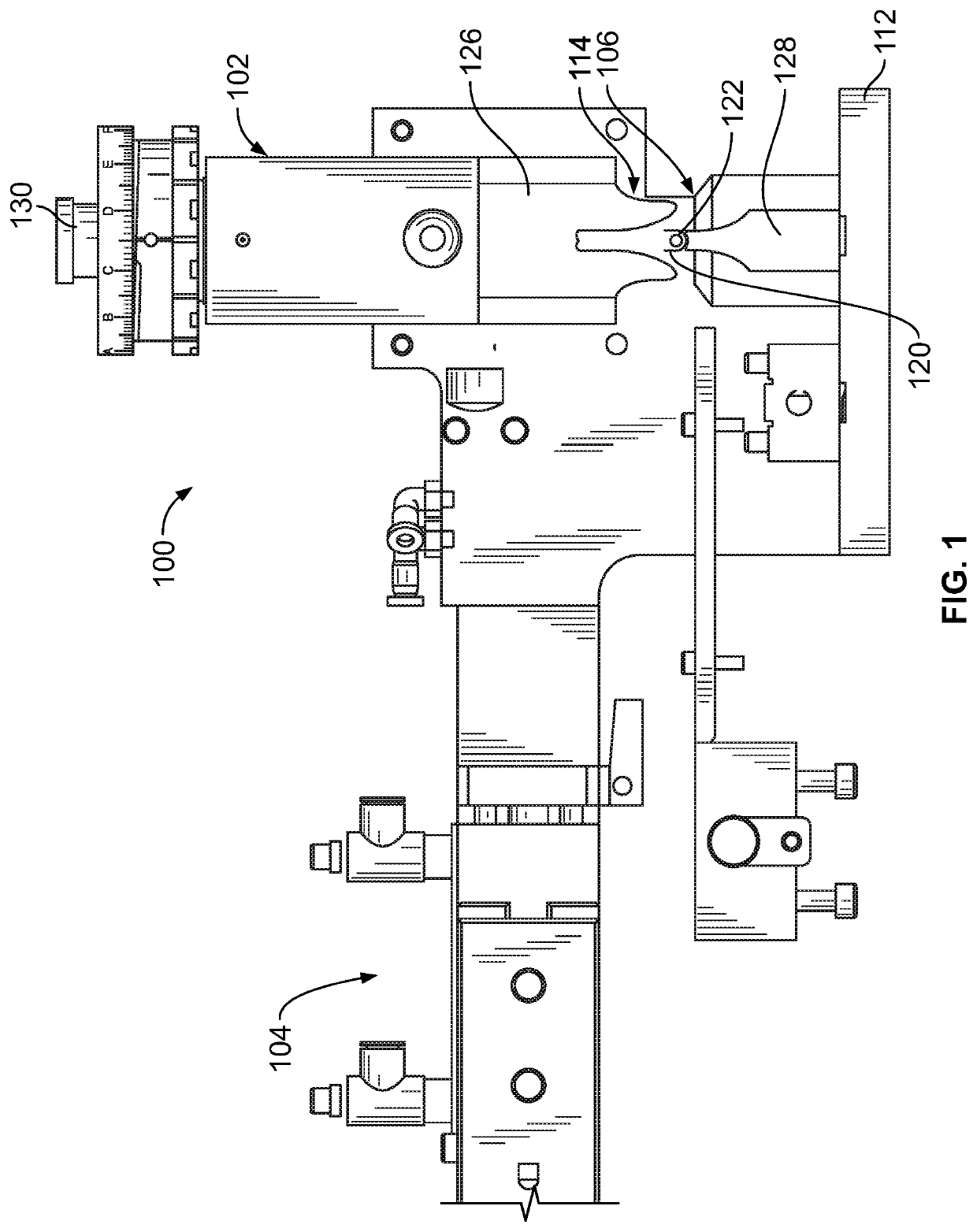
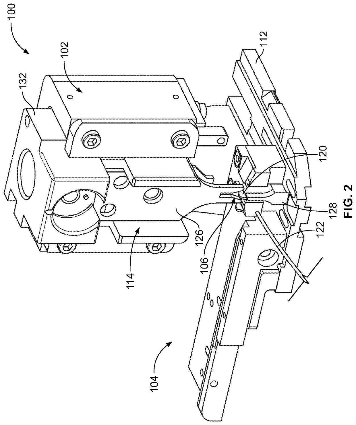
[0022]FIG. 1 is a front view of a terminal crimping machine 100 having a termination tool 102 used for crimping connectors or terminals to wires, however, other types of terminal crimping machines 100 may be used. FIG. 2 is a perspective view of a portion of the terminal crimping machine 100. In the illustrated embodiment, the terminal crimping machine 100 is a terminator or press; however other types of terminal crimping machines may similarly be used, such as a lead maker, a bench machine, a hand crimping tool and the like. Furthermore, while the termination tool 102 is illustrated and described hereinafter with respect to an applicator (may be referred to hereinafter as applicator 102), other types of termination tools 102 may be used depending on the type of terminal crimping machine.

[0023]A terminal feeder 104 is used to feed terminals 120 to a crimping zone 106. In the illustrated embodiment, the terminal feeder 104 is an electrically actuated feeder; however other types of fe...


PUM


Abstract

Crimp tooling includes an anvil and a wire crimper. The anvil includes a base and a tip with a cradle at the tip for supporting a terminal. The anvil has first and second anvil guide surfaces located relative to the cradle. The wire crimper has first and second legs on opposite sides of a crimp slot that receives the cradle and the terminal supported by the cradle. The wire crimper defines a crimp profile in the crimp slot configured to form the terminal during crimping. The first and second legs have first and second wire crimper guide surfaces, respectively. The first and second wire crimper guide surfaces are configured to engage the first and second anvil guide surfaces, respectively, to guide a position of the wire crimper relative to the anvil.

Description

BACKGROUND OF THE INVENTION[0001]The subject matter herein relates generally to crimp tooling for terminal crimping machines for crimping electrical terminals to a wire.[0002]Terminal crimping machines have long been used in the connector industry to effect high-speed mass termination of various cables. It is common practice for the terminal crimping machine to have an interchangeable tooling assembly called an applicator. In general, such terminal crimping machines are referred to as a terminator or press; however, other types of terminal crimping machines may similarly be used, such as a lead maker, a bench machine, or a hand crimping tool. The terminal crimping machines include crimp tooling, such as an anvil and a wire crimper attached to movable ram that is moved relative to the anvil during a crimping stroke to crimp a terminal or connector to an end of a wire. The wire is typically held by a wire clamp during the crimping operation.[0003]However, these known terminal crimping...

Claims


Application Information

Patent Timeline
Patent Type & Authority Patents(United States)
IPC IPC(8): H01R43/048
CPCH01R43/048
Inventor MORRIS, MICHAELDEMING, NEILGERST, MICHAELHOUSER, MATTHEW STEVENCONTE, ALOIS
Owner TE CONNECTIVITY GERMANY GMBH
Why Eureka
Try Eureka