Optical imaging lens
a technology of optical imaging and lens, applied in the field of optical imaging lenses, can solve the problems that the optical lens having both a miniaturized size and a desirable imaging quality cannot be manufactured, and achieve the effect of reducing the system length of the optical imaging lens and achieving the desired optical performan
- Summary
- Abstract
- Description
- Claims
- Application Information
AI Technical Summary
Benefits of technology
Problems solved by technology
Method used
Image


Examples
first embodiment
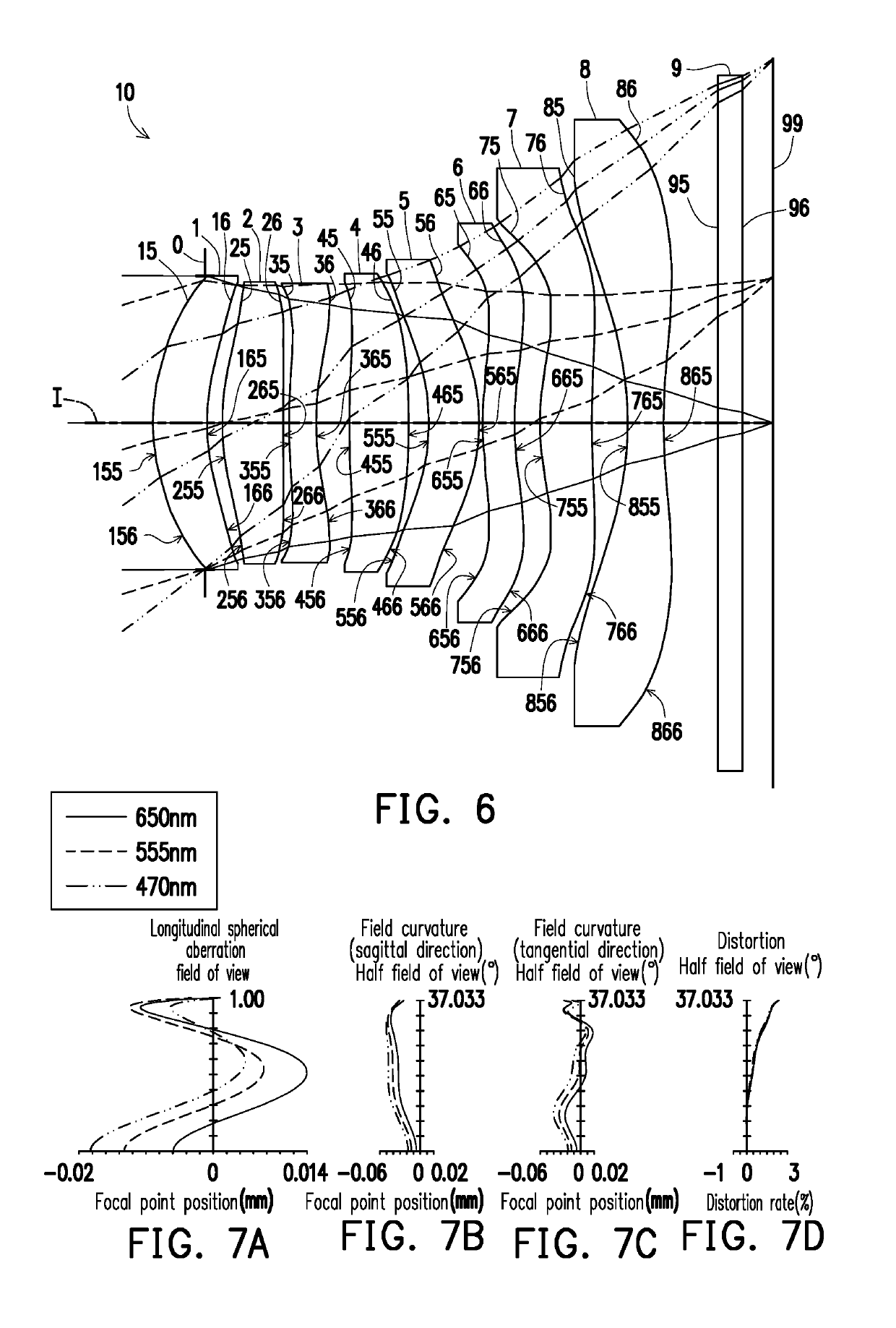
[0138]FIGS. 7B and 7C respectively illustrate the field curvature aberration in the sagittal direction and the field curvature aberration in the tangential direction on the image plane 99 when the wavelength is 650 mm, 555 mm, and 470 mm. In FIGS. 7B and 7C illustrating the field curvature aberrations, focal length variations of the three representing wavelengths in the whole field range fall within a range from −0.05 mm to 0.02 mm, indicating that the optical imaging lens of the first embodiment is able to effectively reduce aberration.
[0139]FIG. 7D illustrates the distortion aberration on the image plane 99 when the wavelength is 650 mm, 555 mm, and 470 mm. FIG. 7D illustrating the distortion aberration indicates that the distortion aberration is maintained within a range from 0 to 2.5%, indicating that the distortion aberration of the optical imaging lens of the first embodiment already satisfies the imaging quality requirement of an optical system.
[0140]Based on the above, compa...
second embodiment
[0142]Detailed optical data of the optical imaging lens 10 are as shown in FIG. 12. In addition, the EFL of the whole optical imaging lens 10 of the second embodiment is 4.275 mm, the HFOV thereof is 36.830°, the Fno thereof is 1.6, the TTL thereof is 5.686 mm, and the image height thereof is 3.238 mm.
[0143]Respective aspheric coefficients of the object-side surfaces and the image-side surfaces of the eight lens elements of the second embodiment in Equation (1) are shown in FIG. 13.
[0144]In addition, relations of important parameters in the optical imaging lens 10 according to the second embodiment are as shown in FIGS. 34 and 35.
[0145]Referring to FIGS. 11A to 11D, in FIG. 11A illustrating the longitudinal spherical aberration, imaging point deviations of the off-axis rays in different heights are controlled within −0.025 mm to 0.015 mm when the pupil radius is 1.3358 mm. In FIGS. 11B and 11C illustrating the field curvature aberrations, focal length variations of the three represe...
third embodiment
[0148]Detailed optical data of the optical imaging lens 10 are as shown in FIG. 16. In addition, the EFL of the whole optical imaging lens 10 of the third embodiment is 4.325 mm, the HFOV thereof is 36.904°, the Fno thereof is 1.6, the TTL thereof is 5.816 mm, and the image height thereof is 3.238 mm.
[0149]Respective aspheric coefficients of the object-side surfaces and the image-side surfaces of the eight lens elements of the third embodiment in Equation (1) are shown in FIG. 17.
[0150]In addition, relations of important parameters in the optical imaging lens 10 according to the third embodiment are as shown in FIGS. 34 and 35.
[0151]Referring to FIGS. 15A to 15D, in FIG. 15A illustrating the longitudinal spherical aberration, imaging point deviations of the off-axis rays in different heights are controlled within −0.019 mm to 0.02 mm when the pupil radius is 1.3515 mm. In FIGS. 15B and 15C illustrating the field curvature aberrations, focal length variations of the three representin...
PUM
| Property | Measurement | Unit |
|---|---|---|
| focal length | aaaaa | aaaaa |
| pupil radius | aaaaa | aaaaa |
| wavelength | aaaaa | aaaaa |
Abstract
Description
Claims
Application Information
 - R&D
- Intellectual Property
- Life Sciences
- Materials
- Tech Scout
- Unparalleled Data Quality
- Higher Quality Content
- 60% Fewer Hallucinations
Browse by: Latest US Patents, China's latest patents, Technical Efficacy Thesaurus, Application Domain, Technology Topic, Popular Technical Reports.
© 2025 PatSnap. All rights reserved.Legal|Privacy policy|Modern Slavery Act Transparency Statement|Sitemap|About US| Contact US: help@patsnap.com