System and console for monitoring and managing pressure testing operations at a well site

a well site and pressure testing technology, applied in the field of oil and gas well drilling and production, can solve the problems of increasing complexity, increasing time and expense to drill a well, and high cost and effort required to respond to a problem during drilling, so as to reduce delays and reduce potential inaccuracies in analysis.

Active Publication Date: 2019-10-08
KONGSBERG OIL & GAS TECH
View PDF53 Cites 2 Cited by
  • Summary
  • Abstract
  • Description
  • Claims
  • Application Information

AI Technical Summary

Benefits of technology

[0018]In one embodiment, the system is installed at the well site, and thus reduces the need to transmit date to a remote site for processing. The well site can be an offshore drilling platform or land-based drilling rig. This reduces delays due to transmitting information to a remote site for processing, then transmitting the results of that processing back to the well site. It also reduces potential inaccuracies in the analysis due to the reduction in the data being transmitted. The system thus allows personnel at the well site to monitor the well site operation in real time, and respond to changes or uncertainties encountered during the operation. The response may include comparing the real time data to the current well plan, and modifying the well plan.

Problems solved by technology

It is well-known that the drilling of an oil or gas well, and related operations, is responsible for a significant portion of the costs related to oil and gas exploration and production.
In particular, as new wells are being drilled into remote or less-accessible reservoirs, the complexity, time and expense to drill a well have substantially increased.
With directional drilling techniques, and the greater depths to which wells are being drilled, many complexities are added to the drilling operation, and the cost and effort required to respond to a problem during drilling are high.
In many cases, the initial geological model may be inaccurate.
Further, since some geological models recite distances based on the distance between two tops, an error in the absolute depth of one top can result in errors in the depths of multiple tops.
Such errors thus affect safety as well as cost and efficiency.
In some cases, the penetration of a high pressure formation can cause a sudden pressure increase (or “kick”) in the wellbore.
If not detected and controlled, a “blowout” can occur, which may result in failure of the well.
Conversely, if the mud weight is too heavy, or the wellbore advances into a particularly fragile or fractured formation, a “lost circulation” condition may result where drilling mud is lost into the formation rather than returning to the surface.
This leads not only to the increased cost to replace the expensive drilling mud, but can also result in more serious problems, such as stuck drill pipe, damage to the formation or reservoir, and blowouts.
Similar problems and concerns arise during other well operations, such as running and cementing casing and tubulars in the wellbore, wellbore completions, or subsurface formation characterizations.
This data can be generated in real-time, but can be enormous, and too voluminous for personnel at the drilling site to review and interpret in sufficient detail and time to affect the drilling operation.
Some of the monitored data may be transmitted back to an engineer or geologist at a remote site, but the amount of data transmitted may be limited due to bandwidth limitations.
Thus, not only is there a delay in processing due to transmission time, the processing and analysis of the data may be inaccurate due to missing or incomplete data.

Method used


Image

  • System and console for monitoring and managing pressure testing operations at a well site
  • System and console for monitoring and managing pressure testing operations at a well site
  • System and console for monitoring and managing pressure testing operations at a well site

Examples


Embodiment Construction

Computing Environment Context

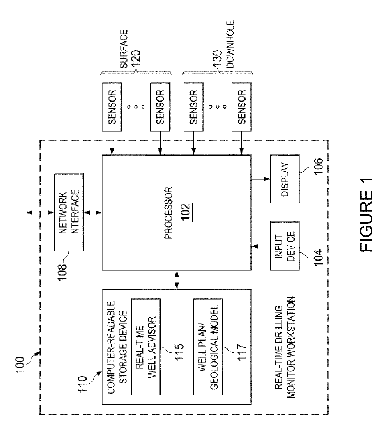
[0064]The following discussion is directed to various exemplary embodiments of the present invention, particularly as implemented into a situationally-aware distributed hardware and software architecture in communication with one or more operating drilling rigs. However, it is contemplated that this invention may provide substantial benefits when implemented in systems according to other architectures, and that some or all of the benefits of this invention may be applicable in other applications. For example, while the embodiments of the invention may be described herein in connection with wells used for oil and gas exploration and production, the invention also is contemplated for use in connection with other wells, including, but not limited to, geothermal wells, disposal wells, injection wells, and many other types of wells. One skilled in the art will understand that the examples disclosed herein have broad application, and that the discussion of any...


PUM


Abstract

A well advisor system and console for monitoring and managing pressure testing operations at a well site. The system may be accessed through one or more workstations, or other computing devices, which may be located at a well site or remotely. The system is in communication with and receives input from various sensors. It collects real-time sensor data sampled during operations at the well site. The system processes the data, and provides nearly instantaneous numerical and visual feedback through a variety of graphical user interfaces (“GUIs”), which are presented in the form of an operation-specific console. The input and data provides information related to pressure testing at a well site.

Description

[0001]This application claims benefit of and priority to U.S. Provisional Application No. 61 / 987,818, filed May 2, 2014, and is entitled to benefit of that priority date. The specification, figures, appendices and complete disclosure of U.S. Provisional Application No. 61 / 987,818 are incorporated herein in their entireties by specific reference for all purposes.FIELD OF INVENTION[0002]This invention relates generally to oil and gas well drilling and production, and related operations. More particularly, this invention relates to a computer-implemented system for monitoring and managing the performance of pressure testing operations at a well site.BACKGROUND OF THE INVENTION[0003]It is well-known that the drilling of an oil or gas well, and related operations, is responsible for a significant portion of the costs related to oil and gas exploration and production. In particular, as new wells are being drilled into remote or less-accessible reservoirs, the complexity, time and expense ...

Claims


Application Information

Patent Timeline
Patent Type & Authority Patents(United States)
IPC IPC(8): E21B33/06G05B23/02E21B44/00E21B47/06E21B17/00
CPCE21B33/06E21B47/06E21B17/00G05B23/0216E21B44/00
Inventor ANDRESEN, PER ARILDHONEY, MARK ADRIANSKARBO, RUNE ARNTEDWARDS, STEPHEN TEANLAST, NIGEL CHARLESMASON, COLIN JAMESWAAGE, TRONDGOMES, PAULO JORGE DA CUNHASANT, RANDALL VASHISHTAPERIYASAMY, SANKARRAPPANJAKOBSEN, THOMAS HESTENESIGLAND, JAN KARERICHARDSON, KEVIN PERRYTJOSTHEIM, SIGURD
Owner KONGSBERG OIL & GAS TECH
Why Eureka
Try Eureka