Applicator

a technology of application and mold, which is applied in the field of applications, can solve the problems of high cost of mold, and change of length or similar dimension of resin molded products,

Active Publication Date: 2019-05-28
WINTRADING CO LTD
View PDF19 Cites 2 Cited by
  • Summary
  • Abstract
  • Description
  • Claims
  • Application Information

AI Technical Summary

Benefits of technology

[0025]With the applicator according to the present invention, even if a plurality of kinds of liquid applying materials of different viscosities and materials accumulated inside are present or the amounts of accumulation of the liquid applying material accumulated in the storage variously differ, the applicator can handle the plurality of kinds of liquid applying materials. Moreover, the applicator with identical shape and identical size can handle the plurality of kinds of the liquid applying materials including the case of different amount of accumulation. Further, even if a plurality of kinds of the liquid applying materials of different viscosities and materials accumulated inside are present or the amounts of accumulation of the liquid applying material accumulated in the storage variously differ, the applicator can handle the plurality of kinds of liquid applying materials. Further, even if respective viscosities of bulk liquid differ, an applicator of identical standard can be used so as not to cause the liquid leakage. Thus, the present invention can provide the excellent effects.

Problems solved by technology

Designing the resin molded product has required many adjustments and has required a high cost for the mold.
Separately manufacturing the absorbing bodies 7 made of the resin molded products whose length or a similar dimension is changed requires the high cost for the mold.
Changing the shape of the applicator so as not to cause a liquid leakage according to the bulk liquid with different viscosities results in an extreme cost increase and is therefore utterly unacceptable.

Method used


Image

  • Applicator
  • Applicator
  • Applicator

Examples


first embodiment

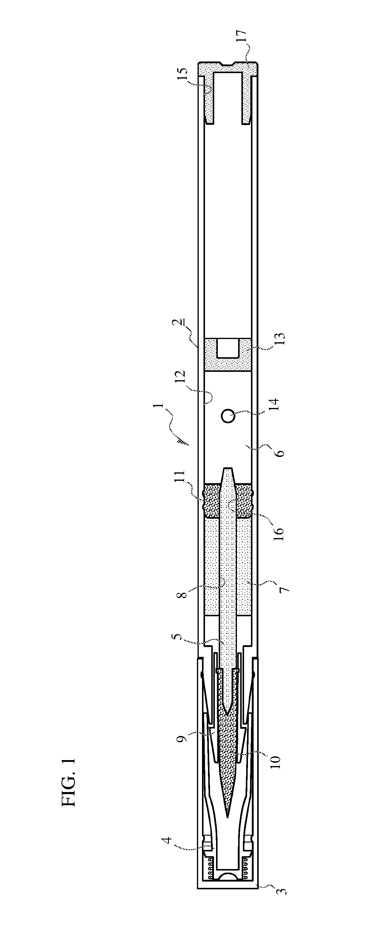
[0035]FIG. 1 is a configuration explanatory view describing a configuration of an applicator 1 according to the present invention.

[0036]The applicator 1 according to the first embodiment of the present invention includes an approximately cylindrical-shaped body 2.

[0037]The applicator 1 also includes a cap 3 and an inner cap 4.

[0038]The body 2 internally holds a core-like application member 5.

[0039]This application member 5 is usually made of a fiber member such that a liquid applying material 6, which will be described later, can be gradually impregnated by, for example, capillarity.

[0040]An absorbing body 7 is used.

[0041]As understandable from FIG. 1, this absorbing body 7 is formed into a columnar shape whose outer peripheral surface has no concavo-convex shape. The absorbing body 7 includes an axially-extending through-hole 8 at a center in the axial direction.

[0042]The application member 5 is inserted through and mounted to this through-hole 8.

[0043]Conventionally, as illustrate...

second embodiment

[0058]Next, the following describes the present invention.

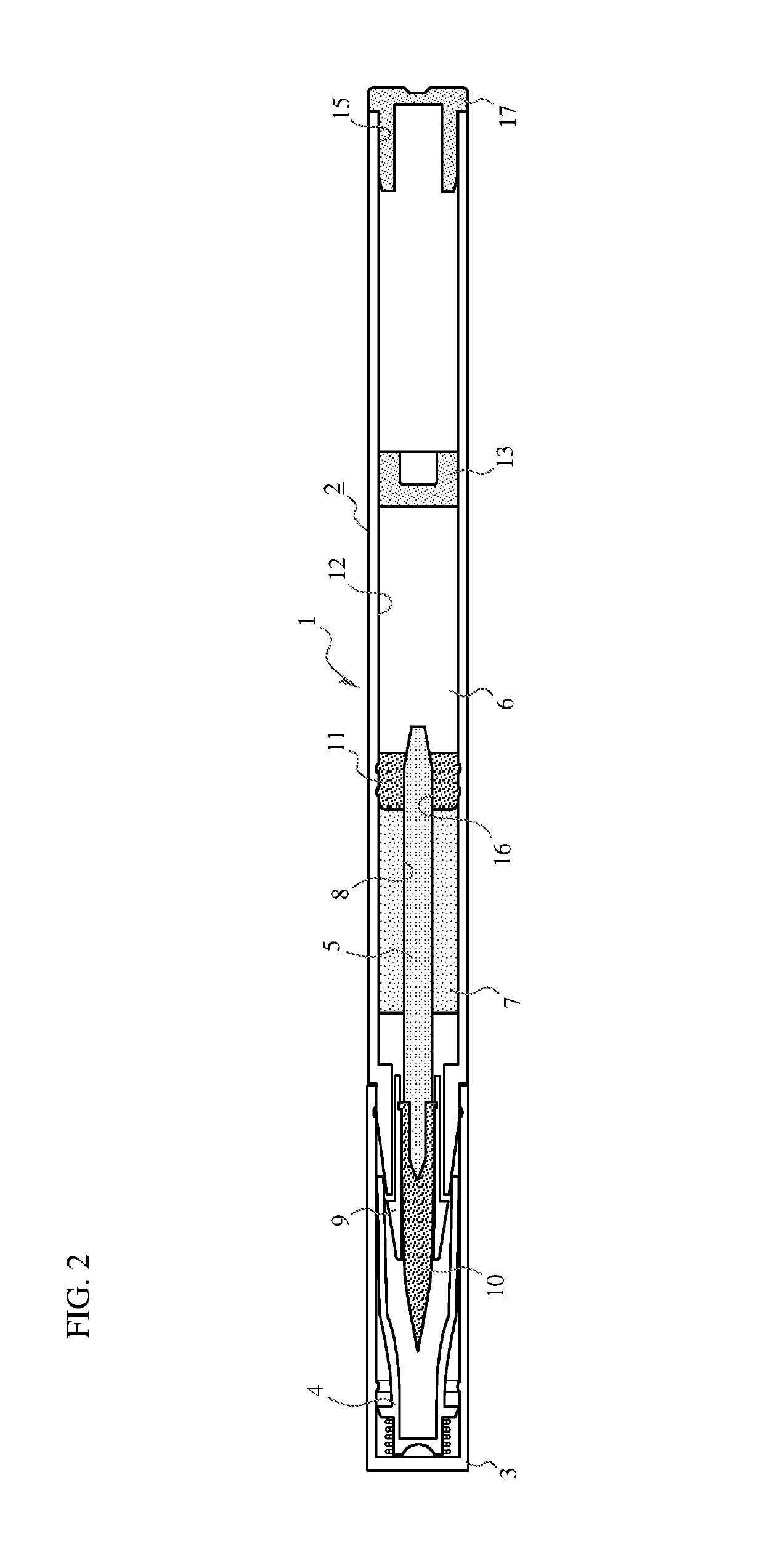
[0059]FIG. 6 and FIG. 7 are configuration explanatory views describing configurations of the applicator 1 according to the second embodiment.

[0060]Similar to the applicator 1 of the first embodiment, the applicator 1 of the second embodiment also includes the approximately cylindrical-shaped body 2, the cap 3, and the inner cap 4.

[0061]The body 2 internally holds the core-like application member 5.

[0062]This application member 5 is usually made of a fiber member such that the liquid applying material 6, which will be described later, can be gradually impregnated by, for example, capillarity.

[0063]As understandable from FIG. 6 and FIG. 7, this absorbing body 7 is formed into a columnar shape whose outer peripheral surface has no concavo-convex shape. The absorbing body 7 includes the through-hole 8, which is inserted through in the axial direction, at the center in the axial direction.

[0064]The application member 5 is inserted...


PUM


Abstract

An applicator that causes a liquid applying material accumulated inside, for example, a cosmetic tool, such as an eye liner and an eyebrow pencil, or a gray-hair partially dyeing tool for hair, an eyebrow, or a similar part, to infiltrate into an application portion to use this liquid applying material for application or drawing from a distal end application portion.

Description

TECHNICAL FIELD[0001]The present invention relates to an applicator that causes a liquid applying material accumulated inside, for example, a cosmetic tool, such as an eye liner and an eyebrow pencil, or a gray-hair partially dyeing tool for hair, an eyebrow, or a similar part, to be infiltrate into an application portion to use this liquid applying material for application or drawing from a distal end application portion.BACKGROUND ART[0002]Conventionally, there has been generally known an applicator (see FIG. 4) such as an eye liner that internally accumulates a liquid applying material. The applicator includes an application member formed of a core material made of a fiber member or a similar member to absorb and infiltrate the liquid applying material. The applicator applies or draws the liquid applying material with a distal end application portion of this application portion.[0003]To adjust an amount of bulk output of the liquid applying material accumulated inside, these appl...

Claims


Application Information

Patent Timeline
Patent Type & Authority Patents(United States)
IPC IPC(8): B43K8/08A45D34/04A45D19/00
CPCA45D34/04A45D19/00B43K8/08A45D34/00A45D40/20A45D2040/201A45D2034/002A45D19/0066A45D34/042A45D2200/1072A45D19/0083
Inventor TAKAHASHI, HIROAKI
Owner WINTRADING CO LTD
Why Eureka
Try Eureka