
Blank for the production of a tooth prosthesis

Active Publication Date: 2019-04-23
STEGER HEINRICH
View PDF16 Cites 2 Cited by
  • Summary
  • Abstract
  • Description
  • Claims
  • Application Information

AI Technical Summary

Benefits of technology

The present invention provides an improved blank for producing tooth prosthesis that simplifies the production process. The invention aims to make the production faster. The dentine boundary of a tooth prosthesis can be clearly seen with the eye when the boundary layer is less than 0.3 mm in thickness. The thicker the boundary layer, the more opaque the material is. Consequently, the boundary layer is sharper and less thick when the material is less transparent. The less the material is opaque, the boundary layer is sharper and less thick.

Problems solved by technology

That is very complicated and expensive and in practice has to be separately established and produced for each individual blank.
A disadvantage with the processes known from the state of the art is the relatively high level of complication and expenditure, in particular if a plurality of parts of a denture set or a plurality of teeth are to be produced.

Method used


Image

  • Blank for the production of a tooth prosthesis
  • Blank for the production of a tooth prosthesis
  • Blank for the production of a tooth prosthesis

Examples


first embodiment

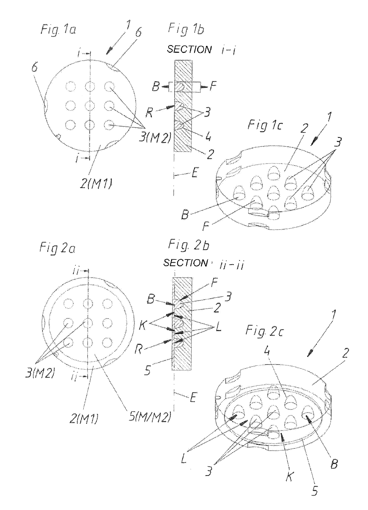
[0035]The configuration of the core regions 3 and the bed 2 can be clearly seen in the section i-i shown in FIG. 1b, the blank 1 in this case having a plurality of separate core regions 3 with separate surfaces F directed in the direction of the bed 2. In this configuration the surface F is of an entirely convex nature. That surface F together with the surface of the bed 2, that is directed in the direction of the core region 3, forms the boundary layer 4. As a surface, however, the core region has not only the surface F directed in the direction of the bed 2 but also the base surface B that faces away from the bed 2. That base surface B is disposed in the base plane E. All base surfaces B of the core regions 3 are arranged in mutually spaced relationship in the blank 1 and lie in the base plane E. In this first embodiment the base surface B forms the outer surface R of the blank 1.

[0036]FIG. 1c is a perspective view illustrating the total of nine core regions 3 with their base surf...

second embodiment

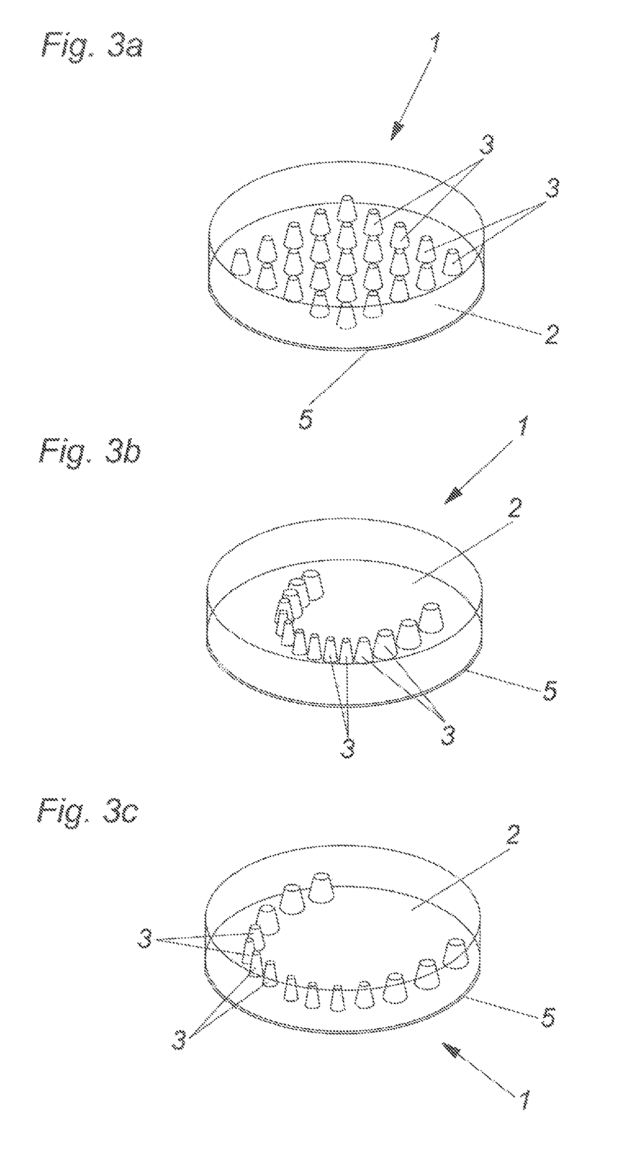
[0037]FIG. 2a shows a plan view of the blank 1. In this case there is additionally provided a basic layer 5 which comprises a material M different from the first material M1, preferably comprising the second material M2.

[0038]As can be seen from the section ii-ii shown in FIG. 2b that basic layer 5 is in one piece with the core regions 3. Once again however—as in the first embodiment of FIG. 1b—the base surfaces B facing away from the bed 2 are all disposed on the same base plane E. In addition, disposed on that base plane E are the contact surfaces K of the bed 2, that are directed in the direction of the basic layer 5. Those contact surfaces K are adjoined by the surfaces L of the basic layer 5, that are directed in the direction of the bed 2. This therefore means that the surface L of the basic layer 5, that is directed in the direction of the bed 2, contacts both the base surfaces B of the core regions 3, that are provided separately and in mutually spaced relationship, and also...


PUM


Abstract

A blank, in particular a dental blank, for the production of a tooth prosthesis, includes a bed of a first material, and at least one core region which is embedded in the bed and which has a different color from the bed and includes a second material. The core region has a surface directed in the direction of the bed, and a boundary layer delimiting the bed relative to the surface of the core region is directed in the direction of the bed. The boundary layer simulates a dentine boundary between a dental enamel and a dentine, and the blank has at least two separate core regions with separate surfaces directed in the direction of the bed.

Description

BACKGROUND OF THE INVENTION[0001]The invention concerns a blank, in particular a dental blank, for the production of a tooth prosthesis. The blank comprises a bed of a first material, and at least one core region which is embedded in the bed and which has a different color from the bed and comprises a second material. The core region has a surface directed in the direction of the bed.[0002]Blanks for the production of a tooth prosthesis, which are made from various materials (for example various plastics) have already been known for some time.[0003]There are, for example, cylindrical disks which in the axial direction comprise various layers of graduated shaded colors. In that way, it is possible to achieve a more natural color variation in dental restoration procedures.[0004]An example of such a variant is disclosed in DE 10 2011 055 393 A1. That specification discloses the manufacture of a blank for artificial teeth, wherein the blank has a homogeneous color transition and the art...

Claims


Application Information

Patent Timeline
IPC IPC(8): A61C13/00
CPCA61C13/0022
Inventor STEGER, HEINRICH
Owner STEGER HEINRICH
Learn More