Differential Unit

a technology of differential units and rotating parts, applied in mechanical actuated clutches, transportation and packaging, gearing, etc., can solve the problems of unnecessary rotational resistance and abrasion of these members, and achieve the effect of suppressing the generation of friction between rotational members

Inactive Publication Date: 2019-03-12
JTEKT CORP
View PDF7 Cites 1 Cited by
  • Summary
  • Abstract
  • Description
  • Claims
  • Application Information

AI Technical Summary

Benefits of technology

[0011]One object of the invention is to provide a differential unit configured to allow or interrupt transmission of a driving force through activation or deactivation of an actuator, and to suppress generation of friction between rotational members while the actuator is deactivated.
[0013]With the differential unit according to the above aspect, it is possible to allow or interrupt transmission of a driving force through activation or deactivation of the actuator, and to suppress generation of friction between rotational members while the actuator is deactivated.

Problems solved by technology

This friction may cause abrasion of these members or cause unnecessary rotational resistance.

Method used


Image

  • Differential Unit
  • Differential Unit
  • Differential Unit

Examples


Embodiment Construction

[0023]Example embodiments of the invention will be described with reference to FIG. 1 to FIG. 5B.

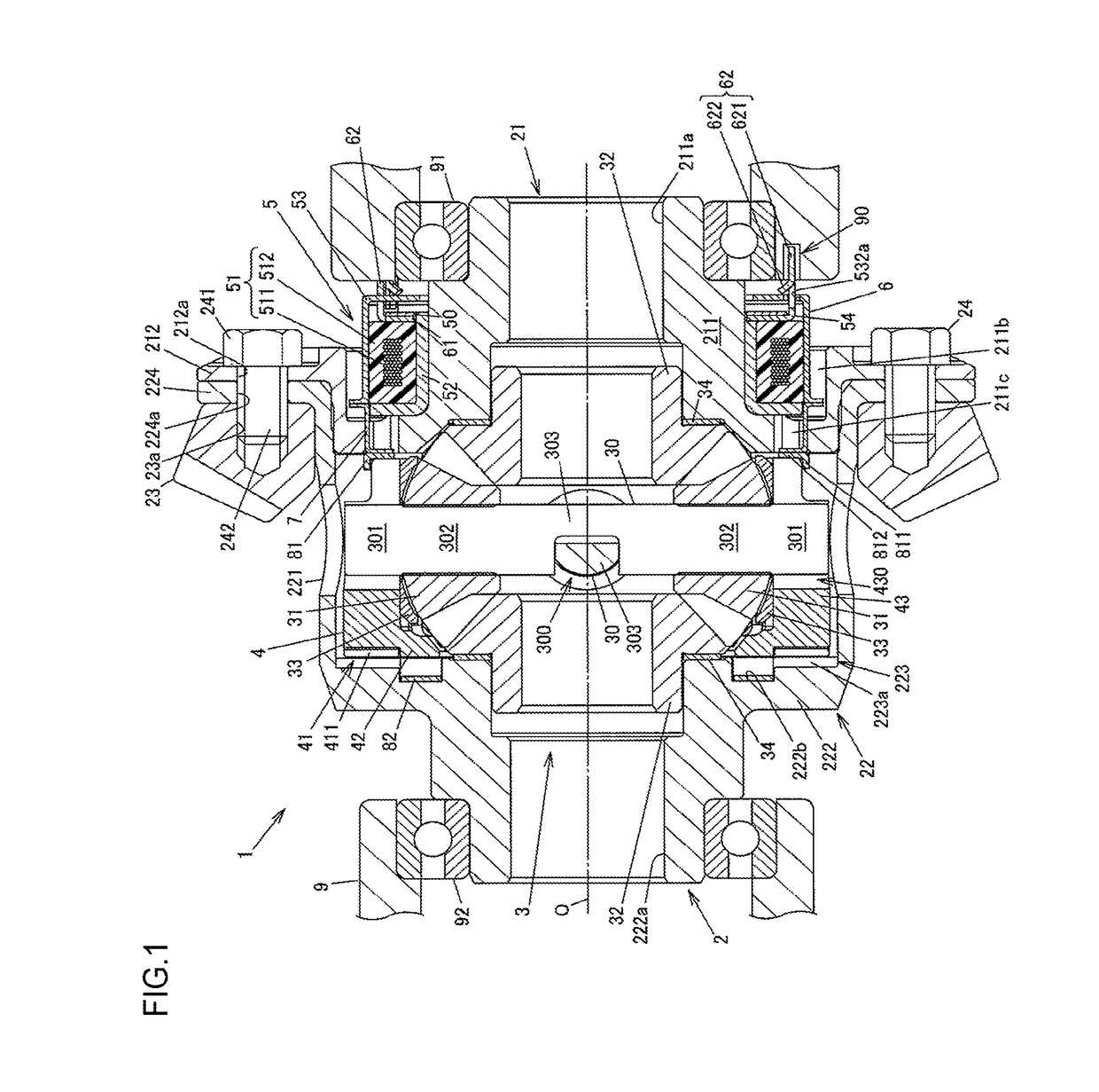
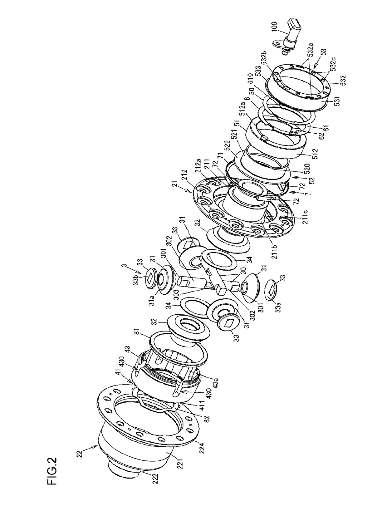
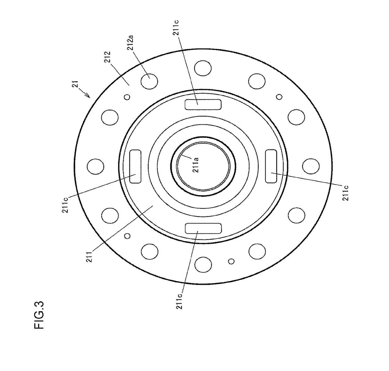
[0024]FIG. 1 is a sectional view illustrating an example of the configuration of a differential unit according to an embodiment of the invention. FIG. 2 is an exploded perspective view of the differential unit. FIG. 3 is a plan view of an inner surface of a first case member of a differential case as seen in an axial direction. FIG. 4 is a perspective view illustrating a second case member of the differential case. FIG. 5A is a partially-enlarged view of FIG. 1, illustrating a deactivated state of an actuator. FIG. 5B is a partially-enlarged view of FIG. 1, illustrating an activated state of the actuator.

[0025]A differential unit 1 is used to distribute a driving force from a driving source, such as a vehicle engine, to a pair of output shafts while allowing the output shafts to rotate at different rotational speeds. More specifically, the differential unit 1 according to the present emb...


PUM


Abstract

A differential unit includes: a differential case; a differential mechanism; a connecting-disconnecting member that connects the differential case to the differential mechanism; an actuator that generates a moving force for moving the connecting-disconnecting member; a moving-force transmitting member that transmits the moving force generated by the actuator to the connecting-disconnecting member; and a wave washer that urges the connecting-disconnecting member in a direction opposite to a direction in which the connecting-disconnecting member is moved by the actuator. The actuator includes a plunger that moves while compressing the wave washer in the axial direction from a first prescribed length using a magnetic force of an electromagnet. A movement of the plunger in a direction away from the connecting-disconnecting member is restricted by a contacting portion of a restricting member. An axial clearance is formed between the plunger and the contacting portion when the wave washer is at the first prescribed length.

Description

INCORPORATION BY REFERENCE[0001]The disclosure of Japanese Patent Application No. 2016-157559 filed on Aug. 10, 2016 including the specification, drawings and abstract, is incorporated herein by reference in its entirety.BACKGROUND OF THE INVENTION1. Field of the Invention[0002]The invention relates to a differential unit including a differential mechanism configured to receive a driving force and output the driving force from a pair of output members while allowing the output members to rotate at different rotational speeds.2. Description of the Related Art[0003]A differential unit configured to receive a driving force and output the driving force from a pair of output members while allowing the output members to rotate at different rotational speeds has been used as, for example, a vehicle differential unit. In some differential units of this kind, transmission of a received driving force to the output members can be interrupted. See, for example, Japanese Patent Application Publi...

Claims


Application Information

Patent Timeline
Patent Type & Authority Patents(United States)
IPC IPC(8): B60K23/04F16D27/112F16D13/76F16H48/22F16H48/34F16H48/08
CPCB60K23/04F16D13/76F16D27/112F16H48/34F16H48/22F16H2048/346F16H48/08B60K17/165
Inventor YOSHISAKA, TADASHIJIN, HEKAMITANI, YASUNORI
Owner JTEKT CORP
Why Eureka
Try Eureka