
Device configuration user interface

a user interface and device technology, applied in the field of computer user interfaces, can solve the problems of cumbersome and inefficient methods for configuring electronic devices, unsuitable for configuring devices with a reduced display size, and existing techniques that use complex and time-consuming user interfaces, etc., to achieve faster and more efficient methods and interfaces, increase efficiency, and improve user satisfaction

Active Publication Date: 2019-02-26
APPLE INC
View PDF356 Cites 76 Cited by
  • Summary
  • Abstract
  • Description
  • Claims
  • Application Information

AI Technical Summary

Benefits of technology

[0006]Accordingly, there is a need for electronic devices with faster, more efficient methods and interfaces for configuring an electronic device. Such methods and interfaces optionally complement or replace other methods for configuring an electronic device. Such methods and interfaces reduce the cognitive burden on a user and produce a more efficient human-machine interface. For battery-operated computing devices, such methods and interfaces conserve power and increase the time between battery charges.
[0022]Thus, devices are provided with faster, more efficient methods and interfaces for configuring an electronic device, thereby increasing the effectiveness, efficiency, and user satisfaction with such devices. Such methods and interfaces may complement or replace other methods for configuring an electronic device.

Problems solved by technology

Some techniques for configuring an electronic device, however, are generally cumbersome and inefficient.
For example, existing techniques use a complex and time-consuming user interface, which may not be suitable for configuring a device with a reduced display size.
Existing techniques require more time than necessary, wasting user time and device energy.

Method used


Image

  • Device configuration user interface
  • Device configuration user interface
  • Device configuration user interface

Examples


Embodiment Construction

[0042]The following description sets forth exemplary methods, parameters, and the like. It should be recognized, however, that such description is not intended as a limitation on the scope of the present disclosure but is instead provided as a description of exemplary embodiments.

[0043]There is a need for electronic devices that provide efficient methods and interfaces for configuring an electronic device. For example, a device may be used to configure settings on another device. In some embodiments, the former device may have a larger display than the later device, which may make it easier for a user to navigate and select settings. Such techniques can reduce the cognitive burden on a user who access event notifications, thereby enhancing productivity. Further, such techniques can reduce processor and battery power otherwise wasted on redundant user inputs.

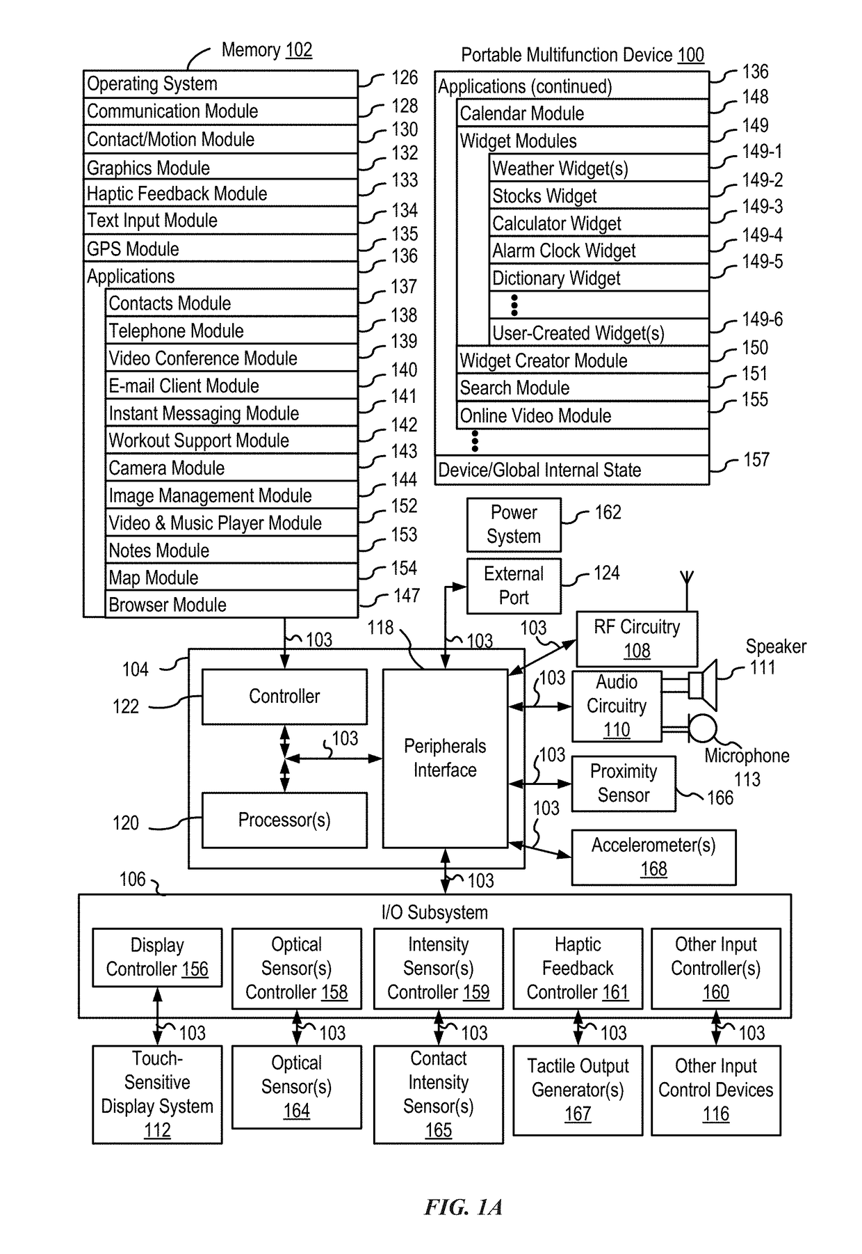
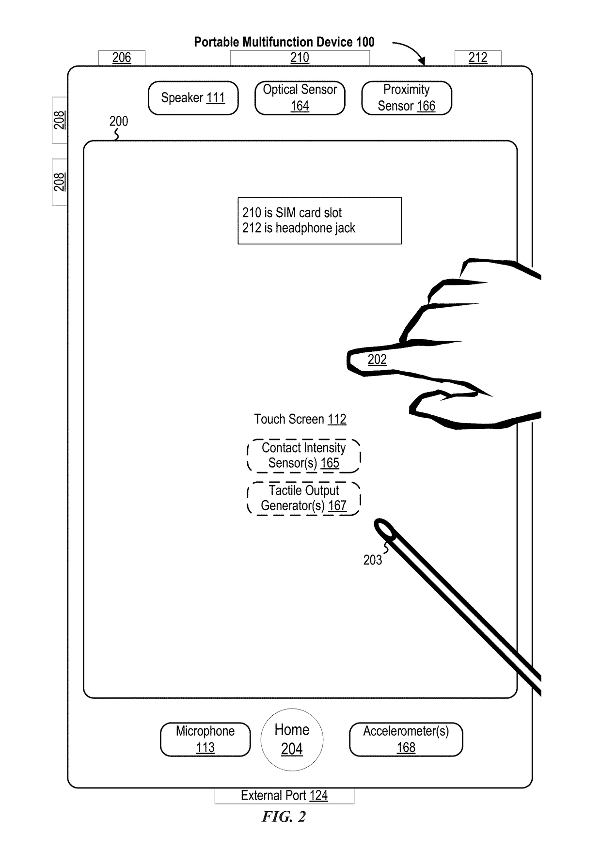
[0044]Below, FIGS. 1A-1B, 2, 3, 4A-4B, and 5A-5B provide a description of exemplary devices for performing the techniques for c...


PUM


Abstract

The present disclosure relates to device configuration user interfaces. An electronic device receives a plurality of alerts comprising information. In response to receiving the plurality of alerts, the device displays local notifications on a first display corresponding to a first set of alerts of the plurality of alerts. The device further sends data representing at least a portion of the plurality of alerts, where the data includes instructions to cause a second electronic device to display remote notifications on a second display corresponding to a second set of alerts of the at least a portion of the plurality of alerts.

Description

CROSS-REFERENCE TO RELATED APPLICATIONS[0001]This application claims priority to U.S. Provisional Patent Application No. 62 / 129,947, filed Mar. 8, 2015, the content of which is hereby incorporated by reference in its entirety.[0002]This application also relates to the following U.S. provisional applications: U.S. Provisional Patent Application Ser. No. 62 / 129,955, titled “Electronic Touch Communication,” filed Mar. 8, 2015, U.S. Provisional Patent Application Ser. No. 62 / 044,961, titled “Electronic Touch Communication,” filed Mar. 8, 2015, U.S. Provisional Patent Application Ser. No. 62 / 044,894, titled “Reduced-Size Interfaces for Managing Alerts,” filed Sep. 2, 2014, U.S. Provisional Patent Application Ser. No. 62 / 129,818, titled “Reduced-Size Interfaces for Managing Alerts,” filed Mar. 7, 2015, U.S. Provisional Patent Application Ser. No. 62 / 044,953, titled “Reduced-Size Notification Interface,” filed Sep. 2, 2014, and U.S. Provisional Patent Application Ser. No. 62 / 129,924, title...

Claims


Application Information

Patent Timeline
Patent Type & Authority Patents(United States)
IPC IPC(8): G06F3/048G06F3/0481G06F3/14H04M1/2745G06F1/16G09G5/12H04M1/725G06F3/0484G06F3/0488G06F3/01H04M1/72412
CPCG06F3/0481G06F1/163G06F3/0484G06F3/0488G06F3/04817G06F3/04842G06F3/04883G06F3/1454G09G5/12H04M1/27455H04M1/7253G06F3/04845H04M2250/22H04M2250/02H04M1/27475H04M1/72412G06F3/01
Inventor YANG, LAWRENCE Y.
Owner APPLE INC
Learn More