
Solar heating apparatus

a solar heating and solar panel technology, applied in the direction of solar heat collector controllers, solar-ray concentration, solar heat collectors moving/orienting, etc., can solve the problem of far less advanced solar power tower development presently

Active Publication Date: 2019-01-29
KING SAUD UNIVERSITY +1
View PDF17 Cites 6 Cited by
  • Summary
  • Abstract
  • Description
  • Claims
  • Application Information

AI Technical Summary

Benefits of technology

The present patent describes a solar heating apparatus with a plurality of reflectors that can concentrate solar radiation on a solar tower or the like. The reflectors are selectively driven and controlled to rotate about multiple axes of rotation. The apparatus includes a longitudinally extending shaft that is selectively rotatable about its longitudinal axis. A pair of laterally extending shafts is secured to the longitudinally extending shaft and is also selectively rotatable about its lateral axis. At least one reflector mount is secured to each of the laterally extending shafts, and at least one optical reflector is mounted on the reflector mount. A continuous belt or chain is mounted on the pair of rotating members, which engage with the longitudinally extending shaft and the laterally extending shafts, allowing the reflector groups to rotate about both the longitudinal and lateral axes simultaneously. The solar heating apparatus can be controlled to efficiently concentrate solar radiation and provide high-quality solar energy.

Problems solved by technology

However, solar power tower development is presently far less advanced.

Method used


Image

  • Solar heating apparatus
  • Solar heating apparatus
  • Solar heating apparatus

Examples


Embodiment Construction

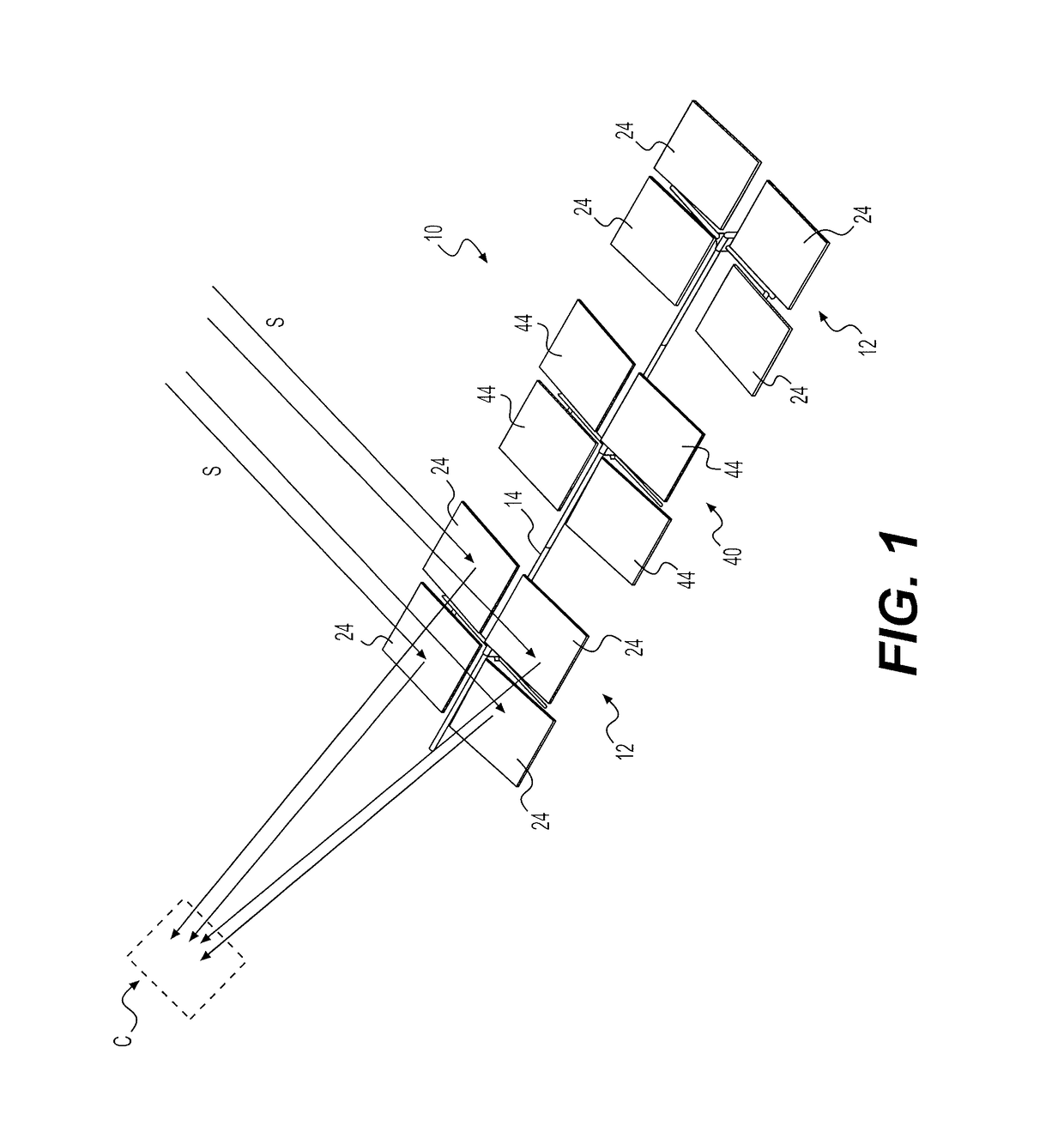
[0020]As shown in FIG. 1, the solar heating apparatus 10 includes a plurality of driven and controllable reflectors 24, 44 for concentrating solar radiation on a solar tower or the like. In FIG. 1, a generalized concentrator target C is shown receiving the reflected solar radiation S. It should be understood that the solar heating apparatus 10 may be used with any suitable type of solar tower, solar concentrator or the like, requiring concentrated reflected solar radiation. Additionally, it should be understood that a typical reflector array consists of hundreds or thousands of individual reflectors (i.e., heliostats). For purposes of clarity and illustration, FIG. 1 only shows one small portion of a typical array, including a pair of end reflector groupings 12 and only a single central, or secondary, reflector grouping 40. In practice, there would be a relatively large number of central, or secondary, reflector groupings 40, and there would also be a relatively large number of repe...


PUM


Abstract

The solar heating apparatus includes driven and controllable reflectors for concentrating solar radiation on a solar tower or the like. Each of the reflectors provided in an array of reflectors is selectively driven to rotate about multiple axes of rotation. A plurality of groupings of optical reflectors, such as mirrors or the like, are mounted about a single, common longitudinally extending shaft, providing simultaneous rotation of the optical reflectors about a longitudinal axis. Through a two-axis bearing associated with each grouping of optical reflectors, the optical reflectors are also mounted on a laterally extending shaft associated with each individual reflector grouping. The laterally extending shafts are linked, each to the other, by a continuous belt or the like, providing selective simultaneous rotation of the optical reflectors about the lateral axis in addition to the simultaneous rotation about the longitudinal axis.

Description

BACKGROUND OF THE INVENTION1. Field[0001]The disclosure of the present patent application relates to solar collectors, and particularly to a solar heating apparatus having reflectors for use with solar power towers, solar heating applications and the like that are selectively and controllably driven to be positioned along multiple axes of rotation.2. Description of the Related Art[0002]Concentrated solar power systems generate solar power by using mirrors or lenses to concentrate a large area of sunlight or solar thermal energy onto a small area. Electricity is generated when the concentrated light is converted to heat, which drives a heat engine (typically a steam turbine) connected to an electrical power generator, or which powers a thermochemical reaction. Heat storage in molten salts allows some solar thermal plants to continue to generate after sunset and adds value to such systems, when compared to photovoltaic panels.[0003]Parabolic trough reflectors for solar concentrators a...

Claims


Application Information

Patent Timeline
Patent Type & Authority Patents(United States)
IPC IPC(8): F24S30/452F24S23/70F24S50/20F24S30/00
CPCF24S30/452F24S2030/133F24S50/20F24S23/70F24S30/455F24S2030/15F24S2023/87F24S2030/136F24S23/77Y02E10/47
Inventor ALMOTLAQ, YOUSEF ABDULLAHBAABBAD, MAZEN ABDULLAHALANSARY, HANY ABDULRAHMANAL AMMAR, ESSAM ABDULAZIZ
Owner KING SAUD UNIVERSITY
Learn More