
Liquid crystal apparatus and television receiver

a technology of liquid crystal display and television receiver, which is applied in the direction of color television details, television systems, instruments, etc., can solve the problems of viewing yellowish colors, and achieve the effect of easy change of the luminance of each light sour

Inactive Publication Date: 2018-11-20
SAKAI DISPLAY PROD
View PDF9 Cites 0 Cited by
  • Summary
  • Abstract
  • Description
  • Claims
  • Application Information

AI Technical Summary

Benefits of technology

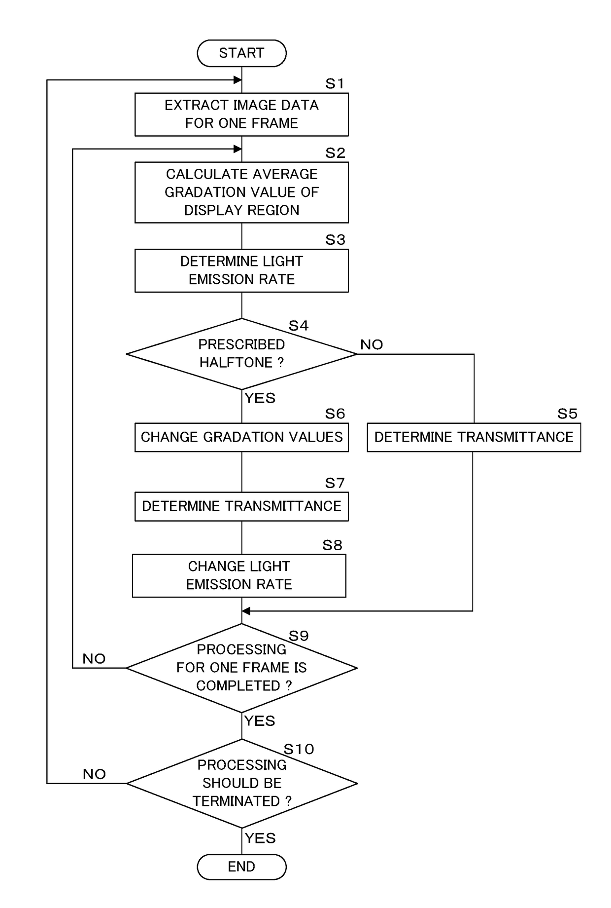
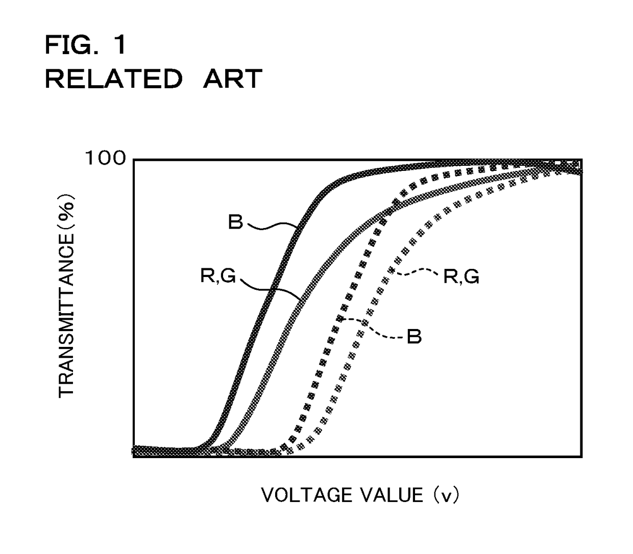
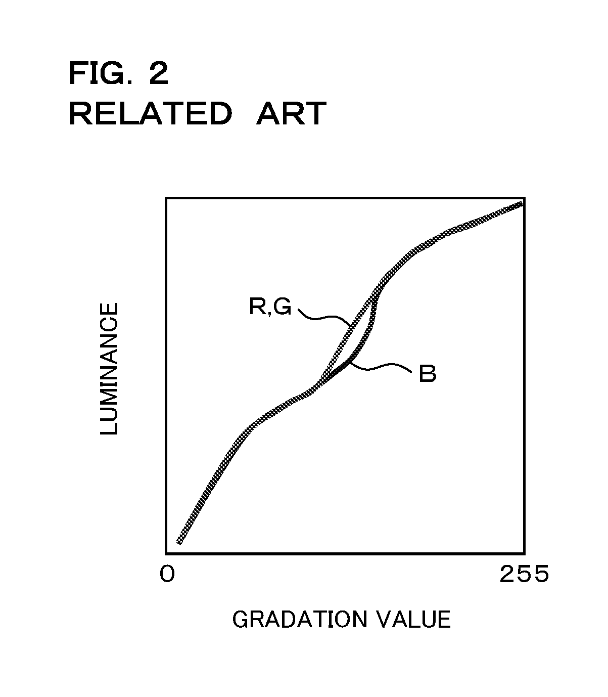
[0009]According to the embodiment of the present invention, the transmittance of the liquid crystal panel (liquid crystal molecules), which is to be controlled by applying the voltage depending on the gradation value within the prescribed range, is controlled so as to be the transmittance depending on the gradation value other than the prescribed range. Thereby, when viewing from an oblique direction, a gradation value within a prescribed range, in which the luminance of a blue pixel is lower than the luminance of a red pixel and a green pixel, is not represented by the liquid crystal panel, thereby suppressing a yellowish color from being viewed when viewing the displayed image from the oblique direction. Further, by increasing / decreasing the luminance of the light source according to a decrease / increase of the gradation value, it is possible to represent the gradation value within the prescribed range.
[0011]According to the embodiment of the present invention, in a configuration that can execute local dimming control to control the luminance for each irradiation region by each light source, the gradation value of the image signal to be displayed is changed for each display region of the liquid crystal panel corresponding to each irradiation region, and the luminance in each irradiation region is changed depending on the change of the gradation value. Thereby, the luminance and the gradation value can be changed for each irradiation region and the display region, such that it is possible to perform fine control.
[0015]According to the embodiment of the present invention, by using a direct type light source, it is easy to change the luminance of each light source depending on the change of the gradation value.
[0017]According to the embodiment of the present invention, a television receiver which suppresses a yellowish color from being viewed when viewing the displayed image from the oblique direction can be achieved.
[0018]According to the embodiment of the present invention, it is possible to suppress a yellowish color from being viewed even when viewing the displayed image with a gradation value within a prescribed range from the oblique direction.

Problems solved by technology

In the gradation value such as the halftone, there is a problem that a yellowish color is viewed when viewing the displayed image from the oblique direction.

Method used


Image

  • Liquid crystal apparatus and television receiver
  • Liquid crystal apparatus and television receiver
  • Liquid crystal apparatus and television receiver

Examples


Embodiment Construction

[0027]Hereinafter, embodiments in which a liquid crystal display apparatus and a television receiver according to the present invention are applied to a liquid crystal television will be described in detail with reference to the drawings illustrating the embodiments thereof. The liquid crystal television of the present embodiment displays a color image based on a color image signal input from an outside. The color image signal may be an image signal from television broadcasts, an image signal read from a recording medium such as a digital versatile disc (DVD) or Blu-ray® Disc (BD), an image signal received via a network or the like.

[0028]FIG. 3 is an exploded perspective view illustrating a configuration of main parts of the liquid crystal television of the present embodiment. The liquid crystal television according to the present embodiment includes a rectangular plate-shaped liquid crystal panel 1 having a display surface on one surface thereof, a backlight 2 which is provided on ...


PUM


Abstract

A liquid crystal television increases or decreases a gradation value when the gradation value of an image signal to be displayed on a liquid crystal panel is within a prescribed range. Further, the liquid crystal television decreases or increases the luminance depending to the gradation value of the image signal based on the increase or decrease in the gradation value. The liquid crystal television applies a voltage depending on the gradation value after the change to the liquid crystal panel, such that a transmittance in the liquid crystal panel is changed (increased or decreased). Further, the liquid crystal television controls each light source to emit light with the luminance after the change, such that the luminance of the light radiated to the liquid crystal panel from the light source is changed (decreased or increased).

Description

CROSS-REFERENCE TO RELATED APPLICATION[0001]This application is the national phase under 35 U.S.C. § 371 of PCT International Application No. PCT / JP2014 / 074279 which has an International filing date of Sep. 12, 2014 and designated the United States of America.BACKGROUND1. Technical Field[0002]The present invention relates to a liquid crystal display apparatus and a television receiver which include a liquid crystal panel and a backlight.2. Description of Related Art[0003]Recently, liquid crystal display apparatuses such as a liquid crystal display and liquid crystal television have been distributed. The liquid crystal display apparatus has a liquid crystal panel and a backlight which irradiates the liquid crystal panel with light from a back side (rear side of a display screen) thereof. The liquid crystal panel includes a plurality of liquid crystal elements (pixels) which are formed by sealing liquid crystal molecules between electrodes disposed to face each other, the plurality of...

Claims


Application Information

Patent Timeline
Patent Type & Authority Patents(United States)
IPC IPC(8): G09G3/34G09G3/36H04N3/12H04N5/74
CPCG09G3/3607G09G3/3406G09G3/3648H04N3/127H04N5/7441G09G2370/08G09G2310/0205G09G2320/0271G09G2320/0653G09G2360/16G09G2300/0443
Inventor YAMAKAWA, RYO
Owner SAKAI DISPLAY PROD
Learn More