
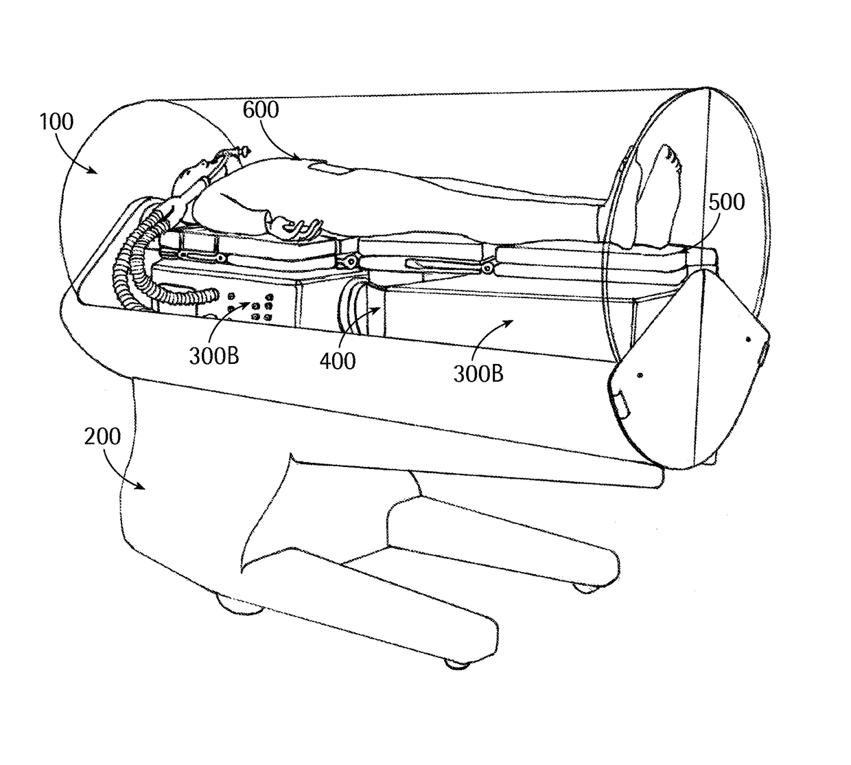
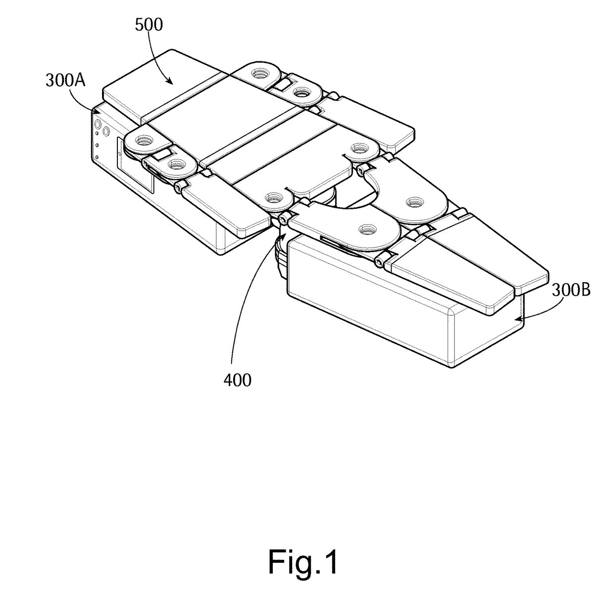
Patient holding hospital unit, patient transportation system and patient transportation and life support system

a technology for patient transportation and hospital units, which is applied in the direction of instruments, process and machine control, treatment rooms, etc., can solve the problems of difficult control of the quality of the sterile environmen

Active Publication Date: 2018-10-23
THE BOARD OF TRUSTEES OF THE UNIV OF ILLINOIS
View PDF48 Cites 2 Cited by
  • Summary
  • Abstract
  • Description
  • Claims
  • Application Information

AI Technical Summary

Benefits of technology

The patent describes a patient holding hospital system that includes a supporting surface for a patient, a life support system, and a control system for managing the functions of the system. The life support system includes a holding fasteners for securely attaching the system to a surgical table or other mount, gas connectors for delivering oxygen and anesthetic gas, and electrically operated devices for supporting the patient's vital functions. The system also includes a power supply unit and a power supply line for supplying power to the control system and other appliances. The patent also describes a patient transportation system that includes a robotic movement system and a protective cocoon for safely transporting and delivering a patient to a surgical table. The system can be easily connected and disconnected from a ground post or other docking member in an operating room or hospital room. The technical effects of the patent include improved safety and efficiency in patient transportation and life support during surgery or medical procedures.

Problems solved by technology

The movement of a surgery patient from his hospital room to anesthesia, to the surgical table and back, involves many people and complicated equipment movement and can be especially cumbersome with the increasing number of obese patients.
Outside the operating room, the quality of the sterile environment is often difficult to control.

Method used


Image

  • Patient holding hospital unit, patient transportation system and patient transportation and life support system
  • Patient holding hospital unit, patient transportation system and patient transportation and life support system
  • Patient holding hospital unit, patient transportation system and patient transportation and life support system

Examples


embodiments

[0098]Various embodiments of the patient transportation and life support system of the present disclosure may be the following ones:

[0099]A1. A patient transportation and life support system comprising:

[0100]a robotic movement system; and

[0101]a detachable surgical table; a detachable modular life support system; and a detachable protective cocoon.

[0102]A2. The patient transportation and life support system according to embodiment A1 wherein the robotic movement system comprises a guidance and control system, a drive system, and a mechanism for attaching the surgical table.

[0103]A3. The patient transportation and life support system according to embodiment A1 wherein the modular life support system is attached to the surgical table.

[0104]A4. The patient transportation and life support system according to embodiment A1 wherein the modular life support system is attached to the robotic movement system.

[0105]A5. The patient transportation and life support system according to embodiment...


PUM


Abstract

A patient holding hospital unit is described. The patient holding hospital unit has a supporting surface configured to receive a patient and a life support system. The supporting surface has a container restrained to the supporting surface that contains an anesthesia machine, reservoirs and related ducts, perfusion devices, an automatic control system, a power supply unit, a power supply line. The container also has dispensing valves arranged on an external surface of the container together with a control interface and the supply valves and electric connector of the power supply line are arranged at a connecting member adapted to be mounted to a base member configured to supply gases under pressure to the reservoirs and power to the control system.

Description

CROSS REFERENCE TO RELATED APPLICATIONS[0001]The present application is the national stage entry of International Application No. PCT / US2014 / 042277, filed on Jun. 13, 2014, which claims priority to U.S. Provisional Application 61 / 834,511 filed on Jun. 13, 2013, which is incorporated herein by reference in its entirety.FIELD[0002]This present disclosure relates to a patient holding hospital unit equipped with appliances for supporting life of a patient laying thereon, that may be enclosed in a protective cocoon supported by a robotic movement system for transporting surgical patients to and from an operating room.BACKGROUND[0003]The movement of a surgery patient from his hospital room to anesthesia, to the surgical table and back, involves many people and complicated equipment movement and can be especially cumbersome with the increasing number of obese patients. Up to six people may be needed to lift a patient from one table to another. One or two people are involved moving the pati...

Claims


Application Information

Patent Timeline
Patent Type & Authority Patents(United States)
IPC IPC(8): A61G10/00A61M16/20A61G13/08A61M5/168A61M16/01A61G13/10
CPCA61G10/005A61G13/08A61G13/104A61G13/107A61M16/01A61M16/20A61M5/168A61G2203/80A61G13/102A61G2203/22A61G1/02
Inventor GIULIANOTTI, PIERVITTORI, ARTUROVOGLER, ANDREAS
Owner THE BOARD OF TRUSTEES OF THE UNIV OF ILLINOIS
Learn More