Cooling device of a vehicle

A car cooling and car body technology, which is applied in the direction of power unit, engine cooling, power unit cooling combination arrangement, etc., can solve problems such as configuration problems, interference, and difficulty in the actual space of the engine compartment, so as to reduce manufacturing costs and manufacture Cost reduction and effect of securing cooling performance

Inactive Publication Date: 2007-06-06
MAZDA MOTOR CORP
View PDF0 Cites 19 Cited by
  • Summary
  • Abstract
  • Description
  • Claims
  • Application Information

AI Technical Summary

Problems solved by technology

[0007] However, in the research and development of automobiles in recent years, it is more and more difficult to ensure the actual space of the engine compartment at the front of the automobile because the comfort of the driver's cabin must be prioritized while ensuring the safety of the automobile in a frontal collision accident. Worrying about the layout of the surrounding auxiliary equipment
In particular, there is basically no sufficient installation space around the transverse engine, and the arrangement of auxiliary machines and manifolds becomes a problem.
[0008] Specifically, when the cooling device configured as in the above-mentioned Patent Document 1 is installed in the engine compartment of a front-engine car, the manifold provided between the cooling device and the engine may interfere with the ventilation door of the fan cover.

Method used


Image

  • Cooling device of a vehicle
  • Cooling device of a vehicle
  • Cooling device of a vehicle

Examples


Embodiment Construction

[0054] Hereinafter, embodiments of the present invention will be described based on the drawings. However, the following description of the best embodiment is merely an example in nature, and the present invention is not intended to limit its applicability or use.

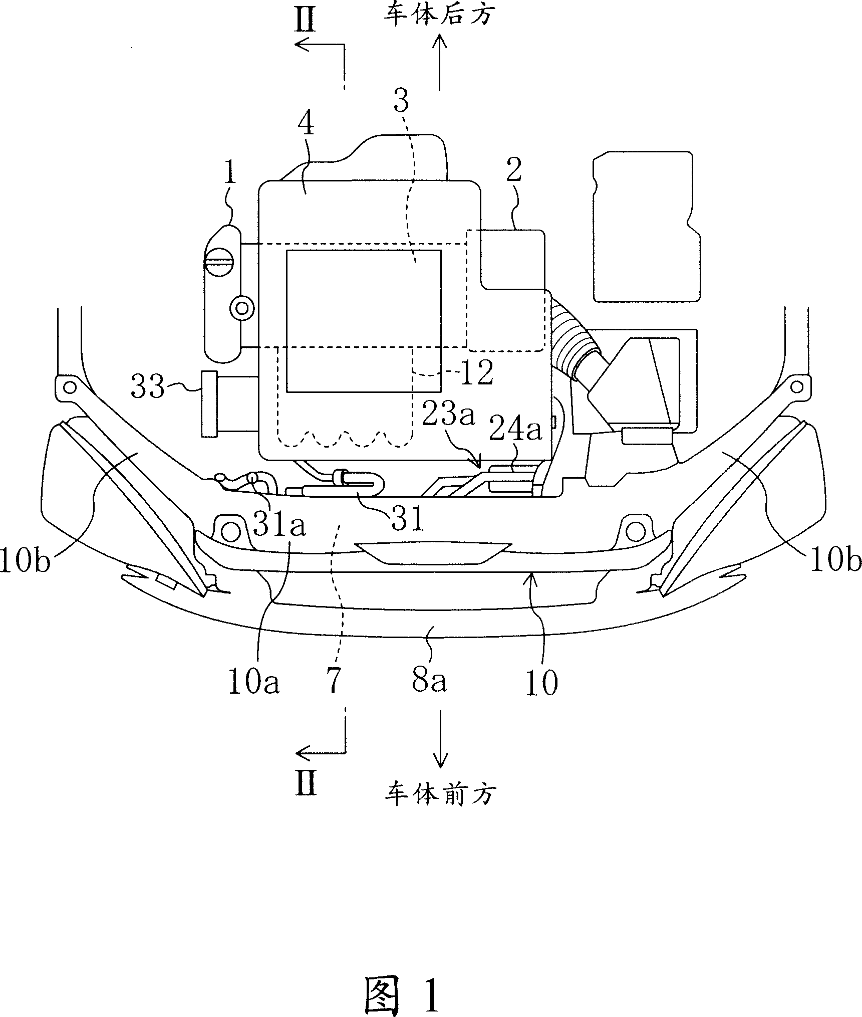
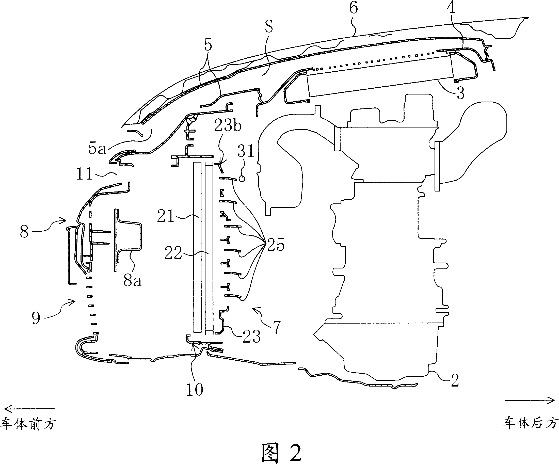
[0055] 1 and 2 show a vehicle body engine compartment front portion including a cooling device according to an embodiment of the present invention. In this engine room, a supercharged engine 1 with an intake manifold 12 disposed on the front side of the vehicle body is mounted horizontally. While the transmission 2 is provided at one end in the vehicle width direction of the engine 1, a metal intercooler 3 is also provided above the engine 1, and the intercooler 3 is slightly higher in the rear side than in the front side. Tilt state setting (refer to Figure 2). Still, in FIG. 1, a part of the machine cover 6 and the bumper covering the engine compartment are omitted.

[0056] The above-mentioned intercooler 3 i...


PUM


Abstract

The present invention provides a cooling device of a vehicle, which includes a fan shroud comprising an opening portion for an electric fan and openings with doors, to properly prevent the doors from interfering with any other parts in an engine room. At a fan shroud 23 constituting a cooling unit 7 are provided a fan opening portion 23a with an electric fan 24 and a door opening portion 23b that includes a plurality of door openings 23c, 23c, ... that are formed substantially vertically in line. A slant portion 23g is formed on the door opening portion 23b in such a manner that positions of the door openings 23c, 23c which are located at a relatively upper level of the door opening portion 23b and the doors 25, 25 provided at these door openings 23c, 23c are located respectively forward relative to those of the other door openings 23c, 23c, ..., and the other doors 25, 25.

Description

technical field [0001] The present invention relates to an automobile cooling device comprising a radiator for cooling cooling water, an electric fan, a fan cover and the like arranged on the front side of the vehicle in the engine compartment. Background technique [0002] Conventionally, as an automobile cooling device, an electric fan is mounted on a radiator or a condenser for cooling cooling water or a refrigerant, and a fan cover is combined. In such a cooling device, while the ambient air is fanned by the electric fan to cool the cooling water in the radiator and the refrigerant in the condenser, air is also sucked in from the outside of the engine compartment to perform ventilation (hot air discharge) in the engine compartment. [0003] However, in the case of the above-mentioned configuration, when the car is running at low speed, the outside air (air outside the engine compartment) sucked in by the electric fan through the fan opening of the fan cover can ensure th...

Claims


Application Information

Patent Timeline
Patent Type & Authority Applications(China)
IPC IPC(8): B60K11/04
CPCF01P11/10F01P2070/50B60K11/085Y02T10/88
Inventor 长野直树小园智哉
Owner MAZDA MOTOR CORP
Why Eureka
Try Eureka