Identifying method of assembling jig of engine
A technology for assembling fixtures and identification methods, which is applied to conveyor control devices, conveyors, conveyor objects, etc., can solve the problem of not being able to assemble fixtures and call out the fixture library, etc., to meet production needs and improve production efficiency.
- Summary
- Abstract
- Description
- Claims
- Application Information
AI Technical Summary
Problems solved by technology
Method used
Image
Examples
Embodiment 1
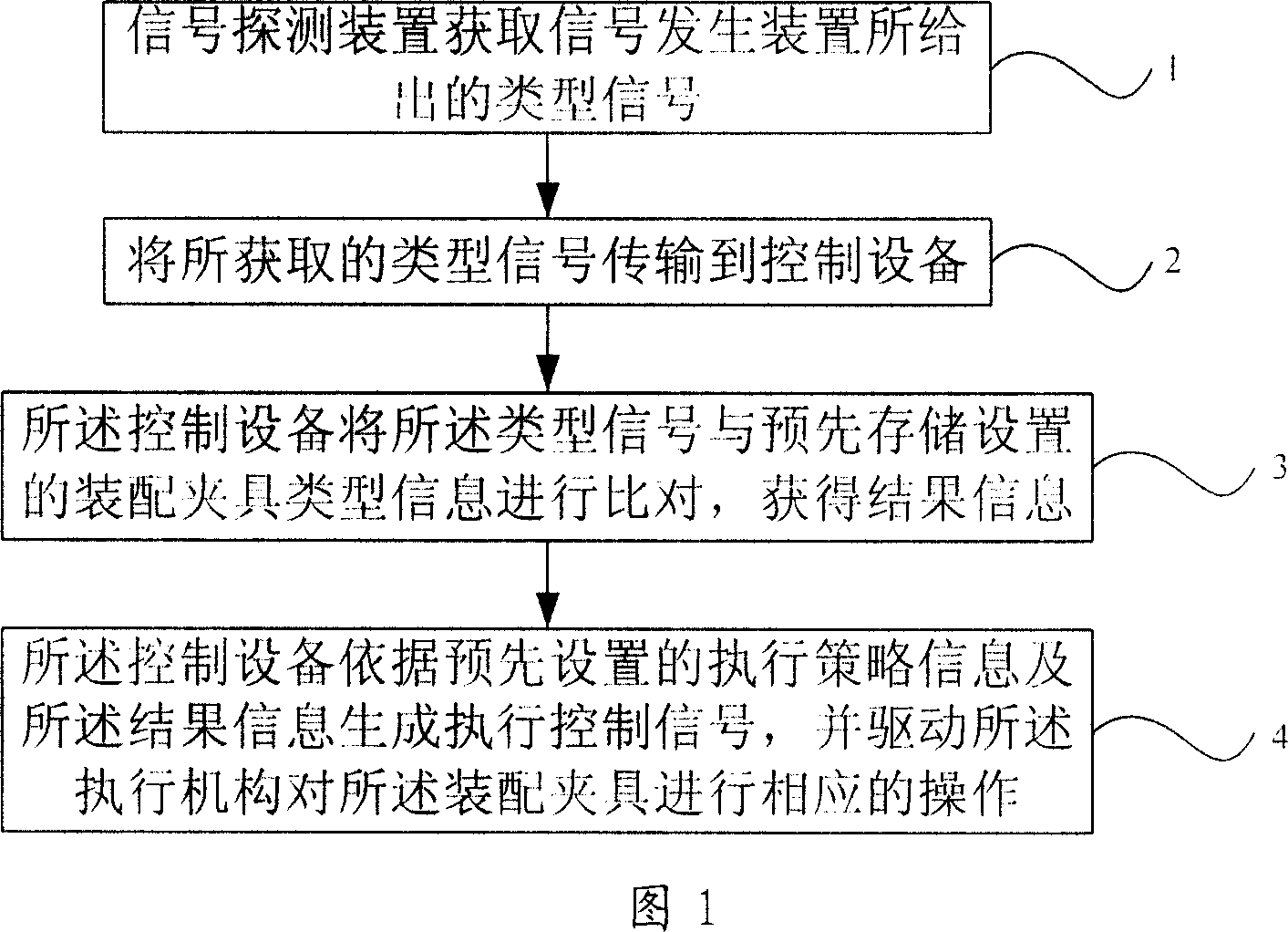
[0019] The flow process of this embodiment is as follows:
[0020] Step 1. The signal detecting device obtains the type signal given by the signal generating device on the assembly fixture;
[0021] Different engines have different jig structures, but since all kinds of jigs are produced on the same production line, all jig bottom plates are the same, and corresponding ones can be set in advance on the designated positions of the bottom plates of various types of assembly jigs. signal generating device;
[0022] Optionally, a stopper for blocking and positioning the assembly fixture is provided at a designated position of the conveying device, and a signal detection device connected to the control device is installed at the corresponding position of the stopper, and the stopper can be an air cylinder The stopper is used to block and position the assembly fixture automatically or manually; or manually remove the assembly fixture from the fixture library, and use a hand-held si...
Embodiment 2
[0031] This embodiment is basically the same as Embodiment 1. In this embodiment, the signal generating device is a row of six signal holes evenly distributed, which are respectively represented by A, B, C, D, E, and F in sequence. The state of the holes can be represented by To distinguish between occlusion or opening, the detailed definition is as follows:
[0032] The first type of fixture: only hole B or hole E is blocked;
[0033] The second type of fixture: only hole C or hole D is blocked;
[0034] The third type of fixture: only holes B and C or holes D and E are blocked at the same time;
[0035] The fourth type of fixture: only holes C and E or holes B and D are blocked at the same time;
[0036] The fifth type of fixture: only holes C, D, E or holes B, C, and D are blocked at the same time;
[0037] The sixth type of fixture: only holes B and E are blocked at the same time;
[0038] Each of the above types of fixtures corresponds to a type of engine;
[0039] W...
Embodiment 3
[0046] This embodiment is basically the same as Embodiment 2, except that the production line is designed as a closed rectangle in practice, and a three-layer fixture storehouse is set in the center of the rectangle, and a hoist is installed at both ends of the fixture storehouse for the clamps to move between the three-storey storehouses. switch. When the fixture is out of the warehouse, first set the type information and quantity of the fixture to be out of the warehouse, and start the out-of-warehouse program. The fixture will run in the warehouse according to the set direction. Install a stopper at the end of the third floor of the fixture library, and each fixture will stop for a short time at this point, and the signal detection device installed under the bottom plate of the fixture will detect the type signal sent by the signal generator and upload it to the control equipment for comparison of the assembly fixture If it matches the set type information, the control devi...
PUM
 Abstract
Description
Claims
Application Information
 - R&D Engineer
- R&D Manager
- IP Professional
- Industry Leading Data Capabilities
- Powerful AI technology
- Patent DNA Extraction
Browse by: Latest US Patents, China's latest patents, Technical Efficacy Thesaurus, Application Domain, Technology Topic, Popular Technical Reports.
© 2024 PatSnap. All rights reserved.Legal|Privacy policy|Modern Slavery Act Transparency Statement|Sitemap|About US| Contact US: help@patsnap.com


