


Quick Research
Generate reliable direction feasibility study reports for your R&D in just a few steps.

Technical Q&A
Discover and master advanced knowledge NOW. Basics, ideas, possibilities, all at once.

Find Solutions
As an expert in R&D theories, this can generate solutions to your technical problems instantly.

Evaluate Feasibility
Analyze your overall solution with one click, know your potential R&D risks in advance.

Monitor Landscape
Get weekly tech updates, stay abreast of the latest tech innovations and key insights.
Tubular member fixing device
A technology for fixing devices and tubular parts, which is applied in the direction of catheters and other directions to achieve the effect of correcting the fixing position and realizing the fixing operation.
- Summary
- Abstract
- Description
- Claims
- Application Information
AI Technical Summary
Problems solved by technology
Method used
Image

Examples
no. 1 example
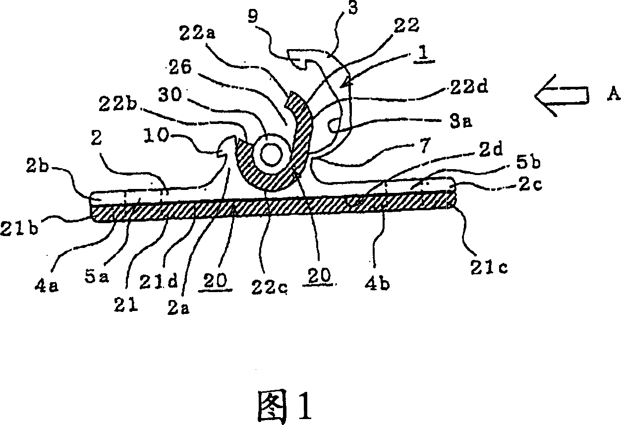
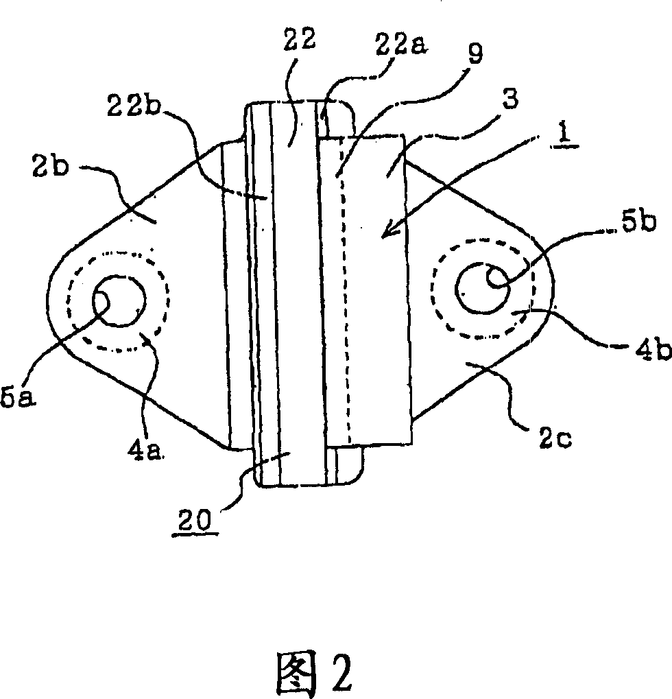
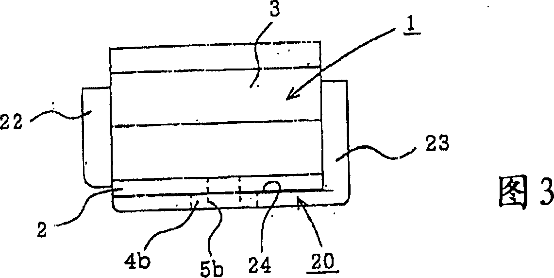
[0054] Fig. 1 is a front view of a catheter fixing device according to a first embodiment of the present invention, the catheter fixing device having an outer fixing member and an inner fixing member integrally assembled with each other. FIG. 2 is a plan view of FIG. 1 . FIG. 3 is a side view of the apparatus of FIG. 1 as seen from direction A. FIG. FIG. 4 is a front view of an external fixation member constituting the catheter fixation device shown in FIG. 1 . FIG. 5 is a plan view of FIG. 4 . FIG. 6 is a side view of the apparatus of FIG. 4 as viewed from direction B. FIG. FIG. 7 is a front view of the internal fixation components making up the catheter fixation device shown in FIG. 1 . 8 is a plan view of FIG. 7, and FIG. 9 is a side view of the device of FIG. 7 seen from direction C. FIG.
[0055] The catheter fixation device includes an outer fixation part 1 (Figs. 4 to 6) and an inner fixation part 20 (Figs. 7 to 9), and the catheter fixation device is formed by comb...
no. 2 example
[0067] Fig. 12 is a front view of the outer fixing member 1 constituting the catheter fixing device according to the second embodiment. In the first embodiment, the first engaging portion 9 is provided on the cover portion 3 of the external fixing member 1, and the second engaging portion 10 is provided on the side of the fitting joint 2a, therefore, the first and second engaging portions 9, 10 engages on the side surface of the catheter fixture. However, in the second embodiment, a pair of cover parts 3a, 3b are arranged to face each other, and these cover parts 3a, 3b are engaged at the top position of the conduit fixing portion. When the catheter fixation device is attached to the skin and the tubular member 30 needs to be adjusted, the device can be opened by squeezing the cover parts 3a, 3b towards each other. In this way, no force is applied perpendicular to the skin, thus achieving a painless and non-irritating replacement of the catheter 30 for the patient.
[0068] ...
no. 3 example
[0072] Fig. 14 is a front view of an inner fixing member 20 according to a third embodiment of the present invention. In the first embodiment, the holding portion 22 is substantially cylindrical and has a constant thickness in the closed state. However, in the third embodiment, the axially oriented protrusions 22e are provided on the outer surface of the substantially cylindrical holding portion 22 at regular intervals. In this example, the thickness of the holding portion 22 other than the protrusion 22e is configured to be thinner than that of the holding portion 22 shown in the first embodiment.
[0073] In the arrangement described above, when the outer surface of the holding portion 22 is covered by the cover portion 3 of the outer fixing member 1, the pressure energy applied through the cover portion 3 can be absorbed. In particular, when the tubular member 30 is thick, the resulting pressure can be absorbed by the protrusion 22 e of the holding portion 22 . In this em...
PUM
 Abstract
Description
Claims
Application Information
 - R&D Engineer
- R&D Manager
- IP Professional
- Industry Leading Data Capabilities
- Powerful AI technology
- Patent DNA Extraction
Browse by: Latest US Patents, China's latest patents, Technical Efficacy Thesaurus, Application Domain, Technology Topic, Popular Technical Reports.
© 2024 PatSnap. All rights reserved.Legal|Privacy policy|Modern Slavery Act Transparency Statement|Sitemap|About US| Contact US: help@patsnap.com