
Method for eliminating the effluence of electricity-conductive drill autoeciousness when measuring mwd tool transient electromagnetic heft

一种导电管、电磁场的技术,应用在用于测井记录的电/磁的探测、肉/鱼的保存、提制黄油等方向,能够解决分辨率有限、MWD工具不方便等问题

Inactive Publication Date: 2007-02-21
BAKER HUGHES HLDG LLC
View PDF6 Cites 4 Cited by
  • Summary
  • Abstract
  • Description
  • Claims
  • Application Information

AI Technical Summary

Problems solved by technology

In addition to limited resolution to oil / water boundaries, such systems are also very long (up to 10-15m), which is undesirable and inconvenient for MWD tools

Method used


Image

  • Method for eliminating the effluence of electricity-conductive drill autoeciousness when measuring mwd tool transient electromagnetic heft
  • Method for eliminating the effluence of electricity-conductive drill autoeciousness when measuring mwd tool transient electromagnetic heft
  • Method for eliminating the effluence of electricity-conductive drill autoeciousness when measuring mwd tool transient electromagnetic heft

Examples


Embodiment Construction

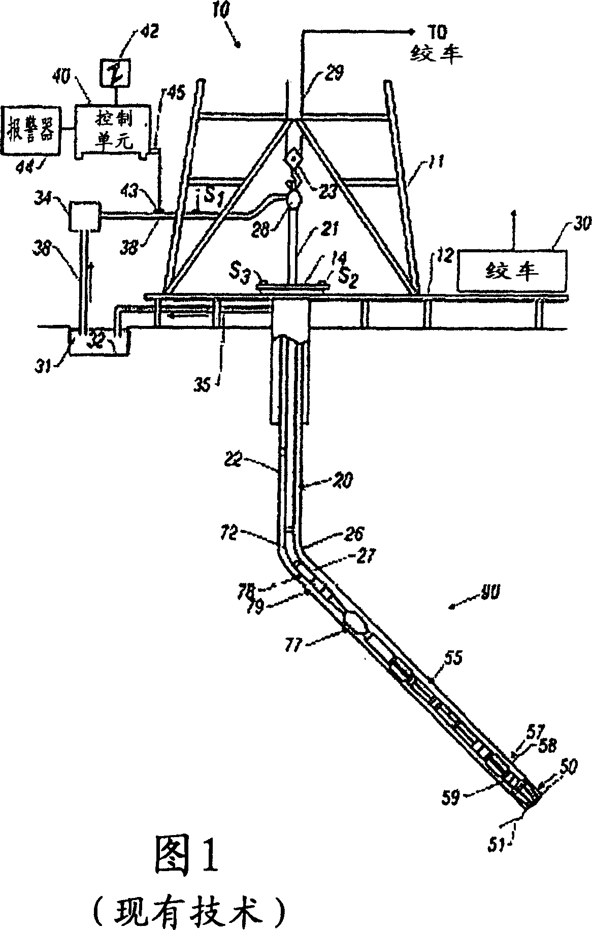
[0027] 1 shows a schematic diagram of a drilling system 10 with a drill string 20 carrying a drilling assembly 90 (also referred to as a bottom hole assembly, or "BHA") in a "wellbore" or "borehole" 26. Shipped for drilling wellbore. The drilling system 10 includes a conventional crane 11 standing on a base plate 12 supporting a wheel 14 rotated at a desired rotational speed by a motive force such as an electric motor (not shown). Drill string 20 includes tubing, such as borehole tubing 22 or a coil of tubing, extending from the earth's surface down to a borehole 26 . The drill string 20 is pushed into the wellbore 26 when the drill pipe 22 is used as a conduit. However, for coiled tubing applications, a tubing injector, such as an injector (not shown), is used to move the tubing from its source, such as a reel (not shown), to the wellbore 26 . The drill bit 50 mounted to the end of the drill string rotates to break up the geological formations to drill the borehole 26 . If...


PUM


Abstract

An emitter of the bottom hole assemble(BHA)is used for generating transient state electromagnetism signal in the earth terrane. A receiver of the BHA is used receives the signals indicating the stratum resistivity and the distance to the stratum boundary. The shaft of the emitter and the receiver can be parallel or form angle with the shaft of the BHA. The emitter and the receiver are arranged on the pipe containing the incisal path BHA damping part for attenuating vortex. The damping part may comprise nonelectrical conductivity material, such as ferrite, on the outer surface.

Description

technical field [0001] The invention relates to the field of electromagnetic induction logging. More particularly, the present invention is a method of reducing the effect of conductive boreholes on resistive signals during transient electromagnetic phenomena. Background technique [0002] Electromagnetic induction resistivity equipment can be used to determine the electrical conductivity of formations surrounding a wellbore. For example, an electromagnetic induction logging device is described in US Patent No. 5,452,761 issued to Beard et al. The device described in Beard's '761 patent contains a transmitter coil and a plurality of receiver coils coaxially spaced apart along the device housing. An alternating current flows through the transmitter coil. The voltage in the receiver coil induced by the alternating magnetic field induced in the formation can then be measured. The magnitude of a certain phase component of the induced receiver voltage is related to the conduc...

Claims


Application Information

Patent Timeline
Patent Type & Authority Applications(China)
IPC IPC(8): G01V3/28A23B4/03A23C15/04
CPCA23B4/031
Inventor 格雷古利·B·伊兹科维奇
Owner BAKER HUGHES HLDG LLC
Learn More