
Vibration-damping structure of electronic device

A technology of electronic devices and vibration-damping structures, which is applied to the structural parts of electrical equipment, electrical components, etc., and can solve problems such as fatigue cracks on printed circuit boards 13

Active Publication Date: 2006-11-22
DELTA ELECTRONICS INC +1
View PDF0 Cites 0 Cited by
  • Summary
  • Abstract
  • Description
  • Claims
  • Application Information

AI Technical Summary

Problems solved by technology

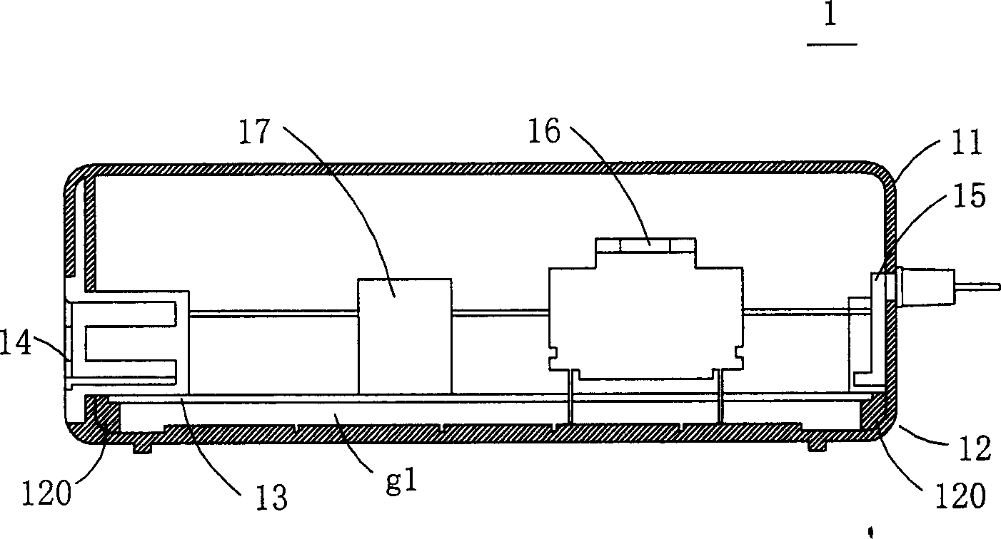
Wherein, the maximum vibration amplitude is mainly located in the region below the heavier element 16, on the contrary, the region below the lighter element 17 has a smaller vibration amplitude, and the nodes generally correspond to the raised elements 120, therefore, it is necessary to reduce the vibration amplitude of the region below the heavier component 16, and if the vibration amplitude exceeds an allowable range, fatigue cracks (fatigue crack) may occur in the printed circuit board 13 question

Method used


Image

  • Vibration-damping structure of electronic device
  • Vibration-damping structure of electronic device
  • Vibration-damping structure of electronic device

Examples


Embodiment Construction

[0041] Some typical embodiments embodying the features and advantages of the present invention will be described in detail in the ensuing description. The invention is capable of various changes in different forms, all without departing from the scope of the invention, and the description and drawings therein are illustrative in nature and are not intended to limit the invention.

[0042] In addition, for the sake of clarity, in the following description, the same elements are denoted by the same reference symbols.

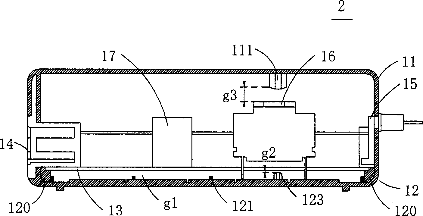
[0043] Please refer to Fig. 2 (a) and Fig. 2 (b), according to a preferred embodiment of the case, a power adapter 2 includes an upper casing 11, and a lower casing 12, the upper casing 11 and the lower casing A space is defined between the shells 12 for accommodating a printed circuit board 13, in addition, an AC power connector 14, a DC power line connector 15, a heavier component 16 and a lighter component 17 are arranged on the space. printed circuit board 13...


PUM


Abstract

The invention relates to a vibration-adsorption device of electric device. Wherein, it comprises the first frame and the second frame, while a space is defined between the first and second frames; and one printed circuit board inside the space; the first weight element is arrange on the first surface of circuit board; the first cylinder on the first frame and under the weight element; and the second cylinder on the second frame and above the weight element.

Description

technical field [0001] The present invention relates to a vibration damping structure of an electronic device, in particular to a vibration damping structure of an electronic device for minimizing vibration impact on a printed circuit board. Background technique [0002] Power adapters, chargers or power supply devices are indispensable electronic devices in many types of electronic products and information products. Please refer to FIG. 1(a), which is a sectional view of a conventional power adapter, wherein the power converter 1 includes an upper casing 11 and a lower casing 12, and the upper casing 11 and the lower casing 12 A space is defined between them to accommodate a printed circuit board 13 . An AC power connector 14 and a DC power line connector 15 are disposed on opposite sides of the printed circuit board 13 , and a plurality of protruding elements 120 are integrally disposed on opposite sides of the inner surface of the lower housing 12 , The periphery of the...

Claims


Application Information

Patent Timeline
Patent Type & Authority Applications(China)
IPC IPC(8): H05K7/00
Inventor 黄瑞庆
Owner DELTA ELECTRONICS INC
Learn More