Disc driving unit and disc equipment using the same
A technology of a disk drive device and equipment, which is applied to the recording of information on a disk, instruments, magnetic recording, etc., can solve the problems of unsuitable reliability of long life, difficulty in ensuring the length of the bearing 118, etc., and achieves cheap components and assembly. The effect of improving performance and ensuring rigidity
- Summary
- Abstract
- Description
- Claims
- Application Information
AI Technical Summary
Problems solved by technology
Method used
Image

Examples
Embodiment approach 1
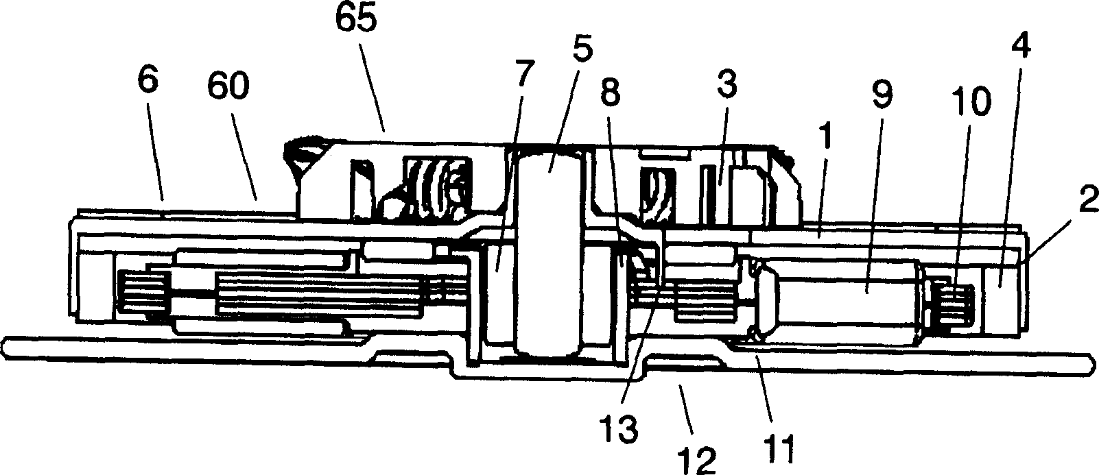
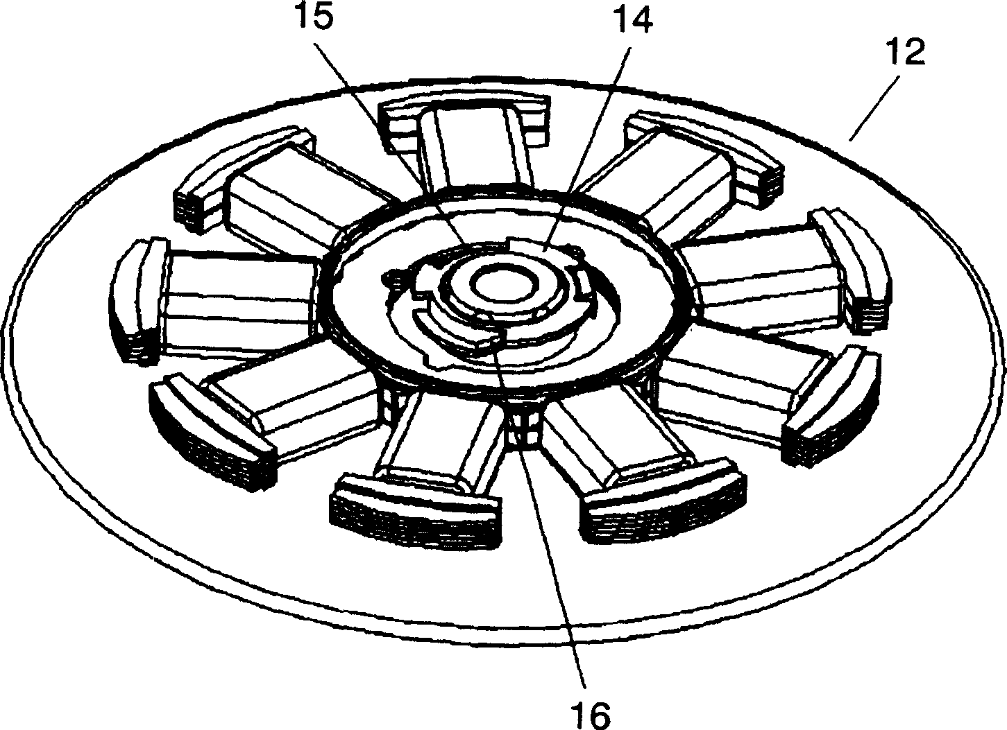
[0054] figure 1 is a cross-sectional view of the structure of the disk rotation motor of the disk drive device according to Embodiment 1 of the present invention; figure 2 yes figure 1 A perspective view of the stator portion of the motor shown; Figure 3A is expressed in figure 1 In the motor shown, the perspective view of the state before the engaging part of the turntable part and the engaged part of the bearing cover are fitted when they are assembled; Figure 3B is expressed in figure 1 In the motor shown, the perspective view of the state when the engaging part of the turntable part and the engaged part of the bearing cover are inserted and fitted; Figure 3C is expressed in figure 1 In the motor shown, the perspective view of the state where the engaging part of the turntable part and the engaged part of the bearing cover are fitted when they are assembled; Figure 4A and Figure 4B It is a top view showing the state when the engaging part of the turntable ...
Embodiment approach 2
[0078] Figure 5 It is a cross-sectional view showing the structure of a disk rotation motor as a disk drive device according to Embodiment 2 of the present invention.
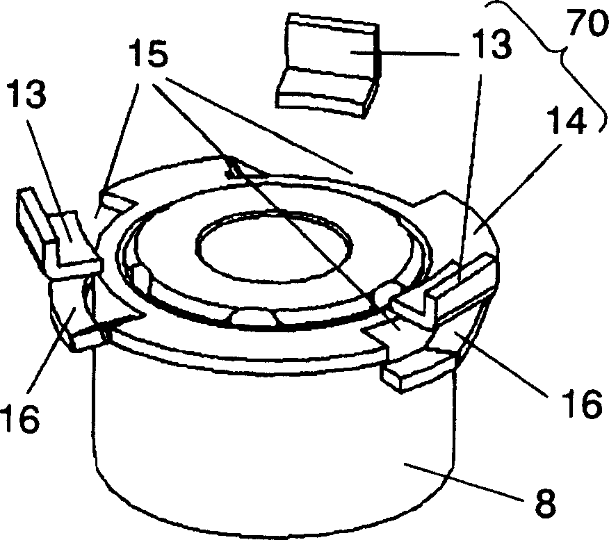
[0079] Figure 5 The difference between the motor 70 shown as the disk drive device 75 according to the second embodiment of the present invention and the above-mentioned first embodiment is that the motor 70 is formed on the bearing cover which can be engaged with the engaging part 22 of the turntable part 21 in the axial direction. The engaged portion 24 of the first engaged portion on 23 forms a two-layer structure in which another member (hereinafter referred to as a shielding ring 25 ) as a second engaged portion is fitted. Furthermore, a plurality of cutouts are respectively formed on the engaged portion 24 (first engaged portion) of the bearing cover 23 and the shielding ring 25 (second engaged portion) of other components, and the shielding ring 25 can be Dynamic.
[0080] Figure 6A ~ Figure 6E ye...
Embodiment approach 3
[0094] Figure 9 It is a perspective view showing the fitting state of the insulator of the stator core and the shield ring of the disk rotation motor of the disk drive device according to Embodiment 3 of the present invention, and shows only the main part of the engaged portion 33 .
[0095] The third embodiment differs from the second embodiment in that the shield ring 31 is lightly fixed by pressing the lower surface of the engaged portion 33 of the bearing cover with the coil spring 32 . With this configuration, the same effect as that of the second embodiment can be achieved in the disk drive device according to the third embodiment of the present invention.
PUM
 Abstract
Description
Claims
Application Information
 - Generate Ideas
- Intellectual Property
- Life Sciences
- Materials
- Tech Scout
- Unparalleled Data Quality
- Higher Quality Content
- 60% Fewer Hallucinations
Browse by: Latest US Patents, China's latest patents, Technical Efficacy Thesaurus, Application Domain, Technology Topic, Popular Technical Reports.
© 2025 PatSnap. All rights reserved.Legal|Privacy policy|Modern Slavery Act Transparency Statement|Sitemap|About US| Contact US: help@patsnap.com