Refrigerator

A refrigerator and deodorization technology, which is used in household refrigerators, coolers, lighting and heating equipment, etc., can solve the problems of reduced cooling performance of refrigerators, reduced deodorization performance, and increased air duct resistance, etc., to improve design aesthetics and improve deodorization. Performance, space saving effect

Inactive Publication Date: 2006-08-23
PANASONIC CORP
View PDF2 Cites 0 Cited by
  • Summary
  • Abstract
  • Description
  • Claims
  • Application Information

AI Technical Summary

Problems solved by technology

[0006] But in the existing structure as shown in Figure 8, although the back of the box of the refrigerator compartment 5 is very simple, but because the back is made of the inner box, the surface material of the pipeline 6 will be exposed, and the beautiful surface cannot be shown. Gloss and transparency etc.
while in Figure 9 In the existing structure shown, the problem is that since a deodorizing filter 15 is provided on the passage section near the suction port 14 of the return pipe 13 of the refrigerator compartment, it not only makes the design of the refrigerator compartment unsightly, but also increases the number of air ducts. Resistance, so that the cooling performance of the refrigerator compartment 10 is reduced
Considering the above-mentioned problems, in order to reduce the air passage resistance of the deodorizing filter 15, there is a method of increasing the mesh size of the filter, but in this case, the contact area is reduced, so that the deodorizing performance is degraded again.
And in another method to prevent cooling performance reduction, that is, in the method of making the deodorizing filter 15 communicate with a part of the return pipe 13 of the refrigerator compartment as a branch, due to the large deodorizing filter 15 flowing into the air duct resistance If the cooling air volume is reduced, the deodorization performance will be reduced.

Method used


Image

  • Refrigerator
  • Refrigerator
  • Refrigerator

Examples


Embodiment approach 1

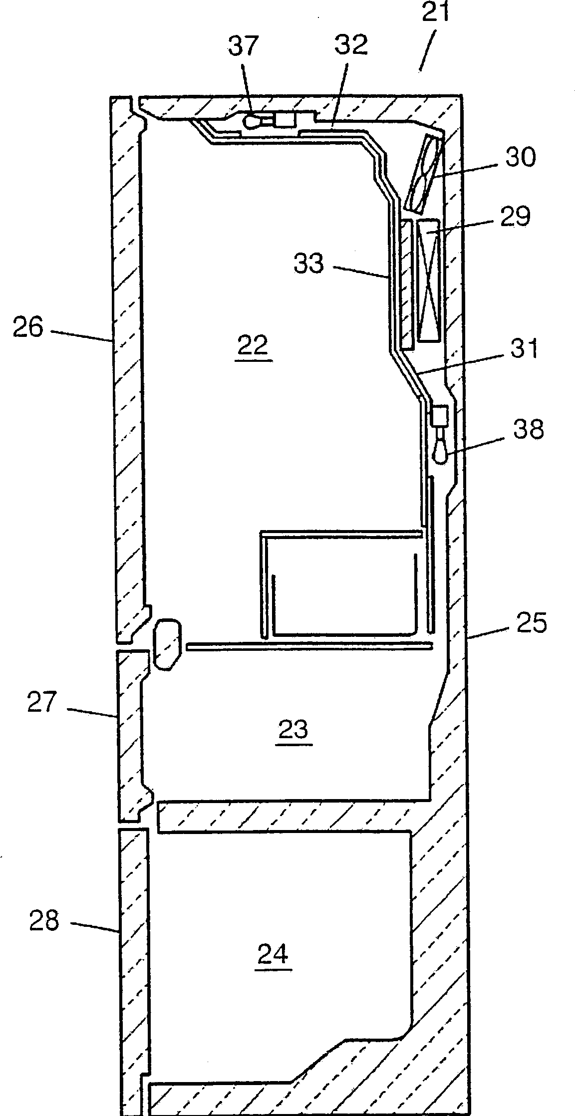
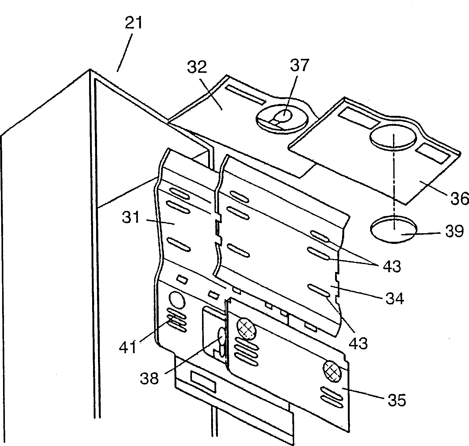
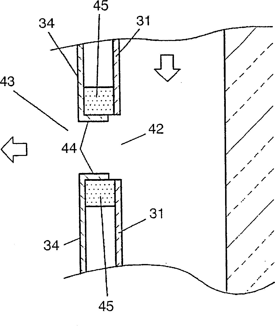
[0020] figure 1 It is a brief cross-sectional view of the refrigerator in Embodiment 1; figure 2 It is an exploded perspective view of the rear parts of the refrigerator-freezing compartment of Embodiment 1; image 3 It is a cross-sectional view near the pipeline discharge port of the refrigerator refrigerator in Embodiment 1; Figure 4 It is a plan cross-sectional view of the refrigerator refrigerator compartment piping and the transparent resin cover of Embodiment 1.

[0021] exist figure 1 Among them, the front of the refrigerator body 21 has an opening, and the interior is divided into a plurality of areas from top to bottom, and a heat insulation box 25, a refrigerator door 26, a refrigerator compartment 22, a vegetable compartment 23, and a freezer compartment 24 are formed from top to bottom Vegetable compartment door 27 and freezer compartment door 28 constitute.

[0022] Refrigerator compartment 22 is provided with cooler 29 for refrigerator compartment and fan...

Embodiment approach 2

[0037]Next, Embodiment 2 will be described.

[0038] Figure 5 It is a perspective view of the pipeline on the back side of the refrigerator freezer of Embodiment 2 observed from the inside; Image 6 It is a perspective view of the pipeline in the back of the refrigerator refrigerator according to the second embodiment viewed from the front; FIG. The same reference numerals are assigned to the same structures as those in Embodiment 1, and detailed description thereof will be omitted.

[0039] exist Figure 5 Among them, the back pipeline 31 is divided into a suction channel 47 and an exhaust channel 48 by a partition rib 49 . A deodorizing device 50 is provided in the air suction channel 47, and the deodorizing device 50 is composed of a deodorizing special fan 51 and a deodorizing catalyst 52, 53. The deodorizing special fan 51 is a box-shaped body called an axial flow fan, which can reduce the installation space. In Embodiment 2, as shown in FIG. 7 , it is installed in a...


PUM


Abstract

The present invention relates to one refrigerator. In the aspiration channel of the back pipeline, one integral deodorizing device comprising special deodorizing fan and deodorizing catalyst is set to ensure the wind rate passing through the deodorizing catalyst. The present invention has raised deodorizing performance of the cold storage chamber while saving space and maintaining the beautiful appearance.

Description

technical field [0001] The present invention relates to piping for cooling the interior of a refrigerator. Background technique [0002] In recent years, due to the diversification of lifestyles, the quality of the design greatly affects the value of the product, so people have been trying to improve the appearance of the refrigerator (see, for example, JP-A-8-152254). For a long time, people have a lot of potential dissatisfaction with the bad smell in the refrigerator. In order to ensure the space in the refrigerator and improve the deodorization performance, it is sometimes necessary to set a deodorization filter in the pipeline for cooling the inside of the refrigerator (for example, refer to JP-P-5 - Bulletin No. 203336). [0003] The conventional refrigerator as described above will be described below with reference to the accompanying drawings. [0004] Fig. 8 is a plan sectional view of a refrigerator compartment of a conventional refrigerator. In FIG. 8 , a foam ...

Claims


Application Information

Patent Timeline
Patent Type & Authority Applications(China)
IPC IPC(8): F25D11/02F25D17/08A61L9/00F25D17/06F25D23/00F25D27/00
CPCF25D2317/067F25D2317/0665F25D2400/18
Inventor 福井博一吉井和之川崎竜也永田晃司
Owner PANASONIC CORP
Why Eureka
Try Eureka