Electric wiring case

A technology for electrical junction boxes and wires, which is applied to electrical components and other directions to prevent damage, improve rigidity, and achieve miniaturization.

Active Publication Date: 2006-05-24
YAZAKI CORP
View PDF0 Cites 7 Cited by
  • Summary
  • Abstract
  • Description
  • Claims
  • Application Information

AI Technical Summary

Problems solved by technology

Therefore, in the conventional electrical junction box, the wire connection part of the terminal fitting protrudes from the main body of the box, and tends to increase in size.

Method used


Image

  • Electric wiring case
  • Electric wiring case
  • Electric wiring case

Examples


Embodiment Construction

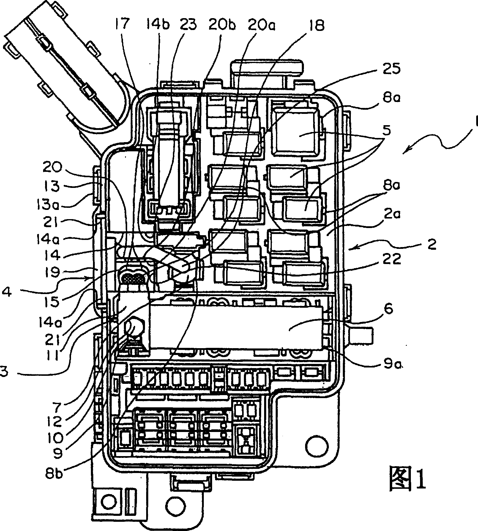
[0036] Below, according to Figure 1 to Figure 5 , an electrical junction box according to one embodiment of the present invention will be described. The electrical junction box 1 shown in FIG. 1 according to this embodiment is mounted on an automobile as a mobile body.

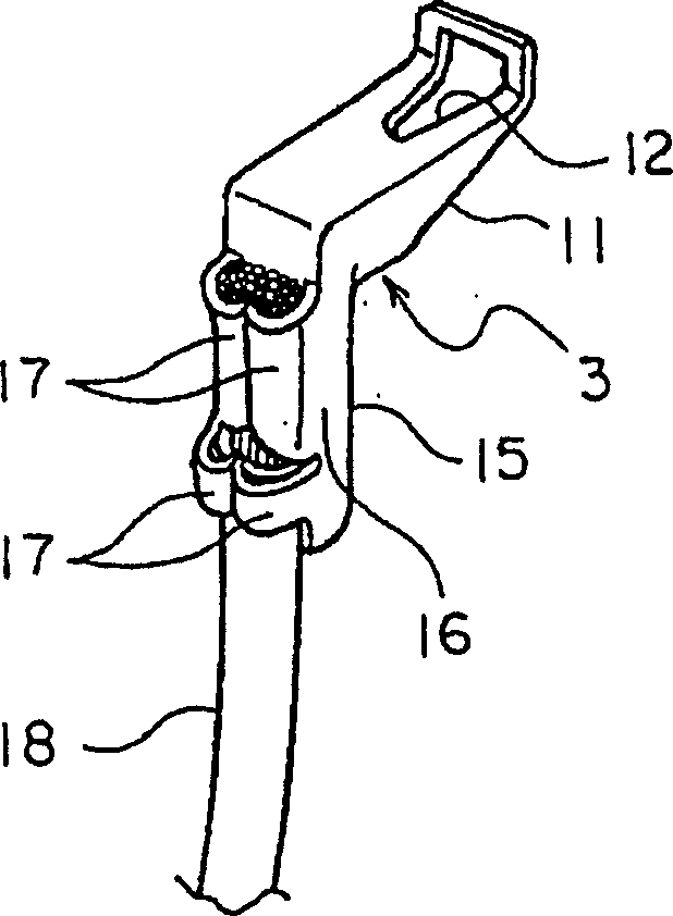
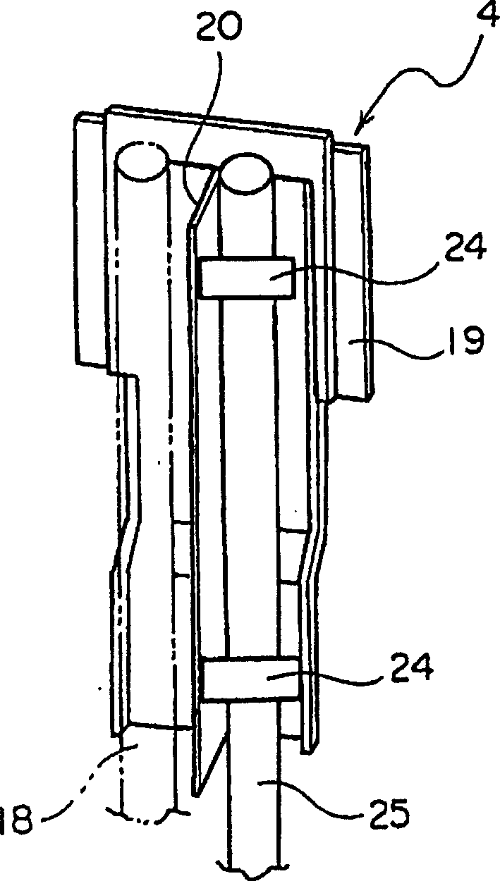
[0037] As shown in FIG. 1 , the electrical junction box 1 has a box main body 2 , a wiring tray not shown, terminal fittings 3 , side covers 4 , and the like. The box main body 2 is made of insulating synthetic resin, and is molded by known injection molding. The box main body 2 is formed in a cylindrical shape (box shape) by a plurality of outer walls 13 .

[0038] In addition, on the upper surface (corresponding to the surface) 2a of the box main body 2 on the front side in FIG. Electrical components such as a melting ring 6 and a connector 7 as an electrical component are fitted. Nuts (not shown) screwed to the bolts 10 are buried in the terminal mounting portion 9 . The terminal fitting part 9 is for...


PUM


Abstract

The present invention provides an electric junction box capable of preventing the electric wire connecting portion of the terminal fitting and the electric wire fitted on the electric wire connecting portion from protruding from the box body, thereby realizing miniaturization. The electrical junction box (1) has a box body (2), a terminal fitting (3) and a side cover (4). The box body (2) has a terminal fitting portion (9) provided on the upper surface (2a) and a groove (14) recessed from the outer wall surface (13a). The terminal fitting (3) has an electrical contact portion (11) and a wire connection portion (15). The electrical contact portion (11) is fitted on the terminal fitting portion (9). The electric wire connection part (15) is fitted with electric wires (18). The box body (2) accommodates the electric wire connecting part (15) and the electric wire (18) in the groove (14), thereby assembling the terminal fitting (3) on the terminal fitting part (9). At this time, the longitudinal direction of the electrical contact portion (11) is parallel to the outer wall surface (13a). The side cover (4) is assembled on the box body (2) in the form of blocking the groove (14).

Description

technical field [0001] The present invention relates to an electrical junction box mounted on automobiles or the like as mobile bodies. Background technique [0002] In general, a mobile vehicle is equipped with various electronic devices such as lamps such as headlights and tail lights, and electric motors such as starter motors and air-conditioning motors. [0003] In order to supply electric power to the above-mentioned various electronic devices, the above-mentioned automobile is equipped with a junction box at an appropriate position. The above-mentioned junction box is composed of a collection of various circuit units such as fuses and relays. [0004] In addition, the junction box sometimes has fuses, relays, bus bars, etc., so it is also called a fuse box, a relay box, or an electrical junction box in general. In this specification, the above-mentioned fuse box, relay box, and junction box are collectively referred to as an electrical junction box below. [0005] ...

Claims


Application Information

Patent Timeline
IPC IPC(8): H02G3/16
Inventor 江川雅利中山拓哉
Owner YAZAKI CORP
Why Eureka
Try Eureka