Permanent magnet voltage-regulation brushless motor

A generator and voltage regulation technology, applied in synchronous machines, electrical components, electromechanical devices, etc., to achieve the effects of good electromagnetic compatibility, compact structure, and light weight

Inactive Publication Date: 2005-12-21
TELLHOW SCI TECH CO LTD
View PDF0 Cites 5 Cited by
  • Summary
  • Abstract
  • Description
  • Claims
  • Application Information

AI Technical Summary

Problems solved by technology

[0003] The purpose of the present invention is to provide a permanent magnet voltage regulation brushless generator to solve the problems of voltage stability and voltage adjustment

Method used


Image

  • Permanent magnet voltage-regulation brushless motor

Examples


Embodiment Construction

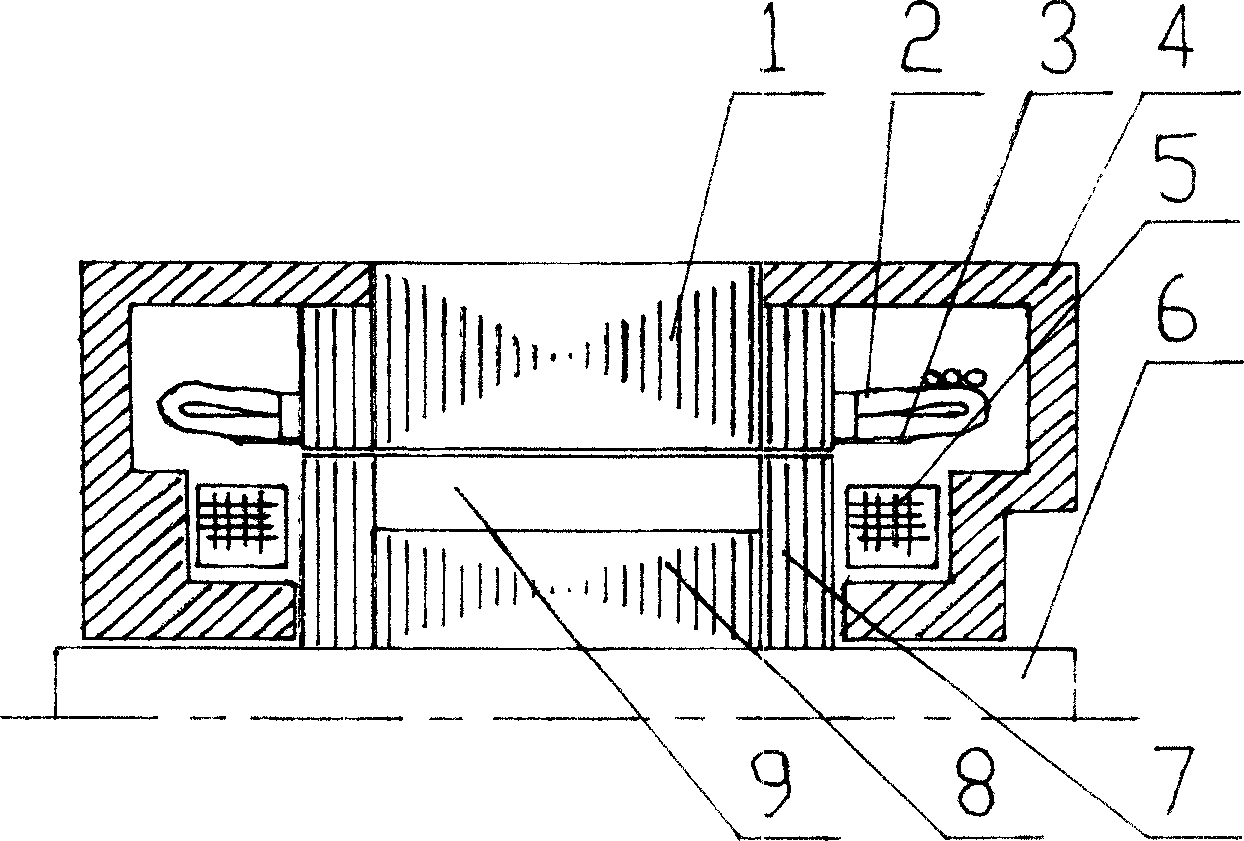
[0008] Such as figure 1 As shown, the present invention includes a stator core (1), a main winding (2), an auxiliary winding (3), a magnetic permeable cover (4), an excitation winding (5), a rotating shaft (6), a rotor end magnetic conductor (7 ), the rotor core (8) and the permanent magnet (9), the main winding (2) and the auxiliary winding (3) are arranged on the stator core (1), and the radial excitation is set in the rotor core (8) Permanent magnet (9), and the special-shaped magnetic conductor (7) of the coaxial assembly of two ends of this iron core, the special-shaped magnetic conductor forms unipolar power generation due to magnetic conductance, for this reason, arranges main winding in the stator iron core, and main winding Induction permanent magnet power generation, also permeance change power generation, the size of the permeance change can be controlled by the ampere-turns of the excitation coil on the two ends of the stator core (4), and the excitation source com...


PUM


Abstract

The disclosed generator includes stator iron core, auxiliary winding, magnetic cover, and rotor core etc. Characters are that main winding and auxiliary winding are setup on the stator core; the magnetic cover and built in excitation winding is setup at two ends of the stator core respectively as well as permanent magnet of radial excitation and magnetizer are setup at the rotor. Advantages of the invention are: (1) only one stator core in brushless, compact, small size, lightweight, and high reliability; (2) permanent magnet as main excitation, auxiliary winding as electric excitation so as to raise excitation efficiency, and lower temperature rise; (3) making motor in permanent magnet regulate and adjust voltage easily by auxiliary electric excitation, good adaptability and good electromagnetic compatibility.

Description

technical field [0001] The invention relates to a permanent magnet voltage regulating brushless generator. Background technique [0002] As we all know, permanent magnet motors bring difficulties to voltage regulation and voltage stabilization. Now people have no good way to solve the problem of voltage stabilization and voltage regulation. Contents of the invention [0003] The purpose of the present invention is to provide a permanent magnet voltage regulation brushless generator to solve the problems of voltage stability and voltage regulation. [0004] The present invention is achieved in this way, it includes stator core, main winding, auxiliary winding, magnetically conductive cover, excitation winding, rotating shaft, rotor end magnetic conductor, rotor core, permanent magnet, and it is characterized in that the stator core is covered with There are main windings, auxiliary windings, magnetic permeable covers ...

Claims


Application Information

Patent Timeline
Patent Type & Authority Applications(China)
IPC IPC(8): H02K21/00
Inventor 林政安
Owner TELLHOW SCI TECH CO LTD
Why Eureka
Try Eureka