
Humidifier

A technology of humidifier and humid air, which is applied in the direction of air humidification system, heating method, lighting and heating equipment, etc. It can solve the problems of increasing the manufacturing cost of the humidifier, restricting the setting of the operating circuit board and the control circuit board, and achieving the realization of the equipment structure. Effects of compactness, high designability, and manufacturing cost reduction

Inactive Publication Date: 2005-05-18
DAINICHI
View PDF1 Cites 6 Cited by
  • Summary
  • Abstract
  • Description
  • Claims
  • Application Information

AI Technical Summary

Problems solved by technology

Moreover, in order to completely eliminate the influence of humidified air, it is necessary to improve the sealing of the air passage, so the moisture-proof performance of the components on the circuit board must be improved, resulting in an increase in the manufacturing cost of the humidifier, while also restricting the operation of the circuit board and Controls the setup of the circuit board, so making the device compact is difficult to solve

Method used


Image

  • Humidifier
  • Humidifier
  • Humidifier

Examples


Embodiment Construction

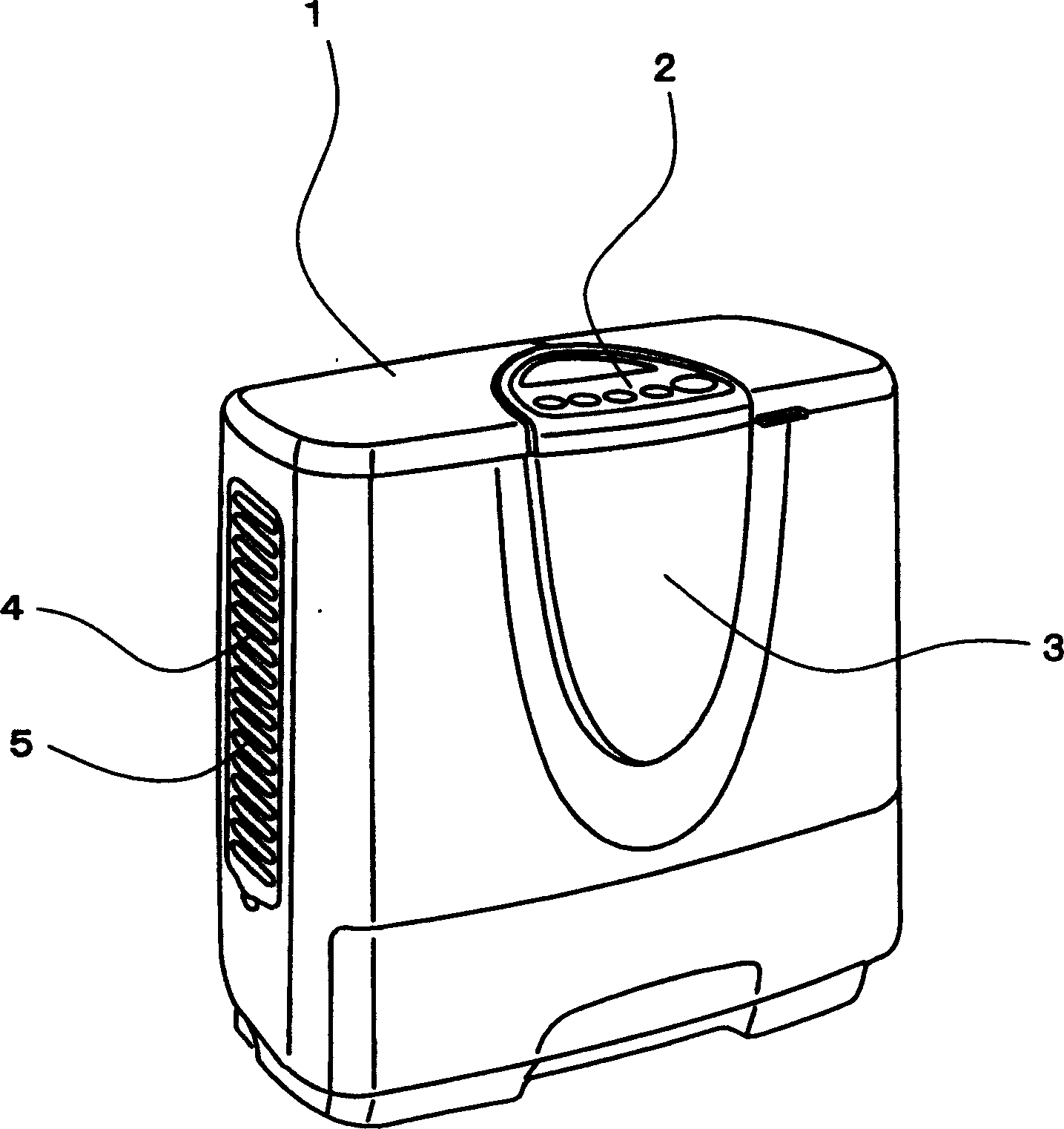
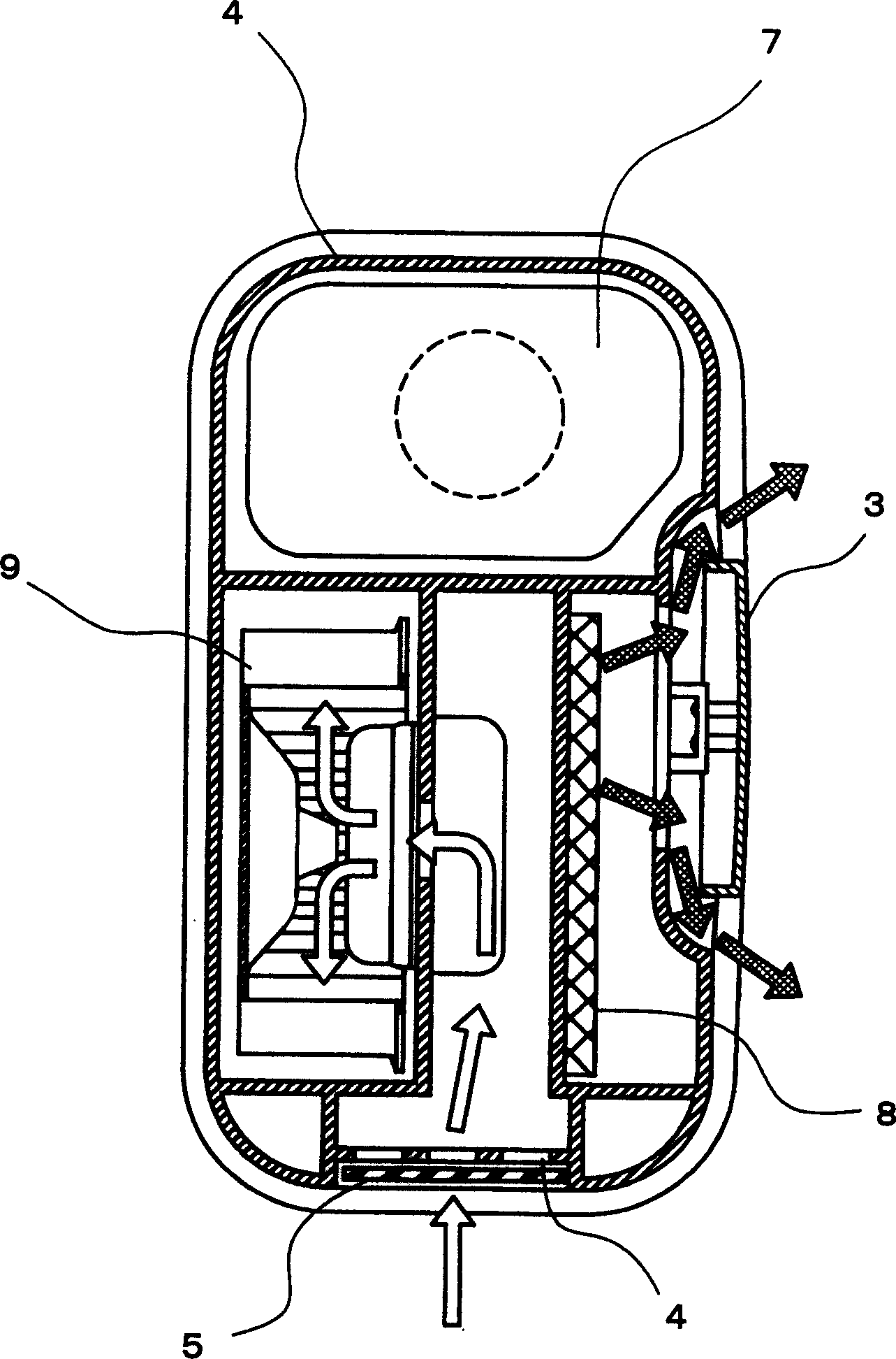
[0022] An embodiment of the present invention will be described below with reference to the drawings. figure 1 is a schematic diagram of an embodiment of the humidifier of the present invention. figure 2 is a longitudinal sectional view of an embodiment of the humidifier of the present invention. image 3 is along the attached figure 2 The cross-sectional view indicated by the middle section line A-A. Figure 4 It is a longitudinal cross-sectional view showing the flow path of air when the air outlet is in an open state in an embodiment of the humidifier of the present invention. Figure 5 It is a detailed view of the flow path of the air from the air inlet in the embodiment of the humidifier of the present invention.

[0023] According to attached figure 1 , Code 1 represents the body of the humidifier. Code 2 represents the operation panel arranged on the upper part of the body 1 for controlling the operation of the humidifier. On the lower part of the operation pa...


PUM


Abstract

The invention relates to a humidifier, which solves the technical problem of making the equipment compact while the electrical components are not affected by the humidified air. Air, the air outlet that blows humidified air upward and sideways in the open state, is provided with a suction port that sucks indoor air into the body, and is provided with a fan that sucks air from the suction port and sends it to the air outlet. There is a water tank part for storing water inside, a vaporization filter that absorbs the water in the water tank part and the air is sent by the fan to vaporize the water, an operation circuit board with an operation switch and an indicator light, and a storage tank. The operation circuit board accommodating part of the operation circuit board constitutes an air passage through the route from the suction port to the blowing port, and in the humidifier provided with a water supply tank for supplying water to the water tank part, there is a An air introduction port for introducing a part of indoor air sucked into the operation board accommodating part and increasing the internal pressure of the operation board accommodating part. The present invention can be used in places requiring humidification such as indoors.

Description

technical field [0001] The invention relates to a humidifying device, in particular to a humidifier for preventing indoor drying. Background technique [0002] Humidifiers in the prior art such as Figure 6 As shown, the code 51 represents the body of the humidifier, and the code 52 represents the water tank part, and the water tank part 52 is used to store the water inside the body. Reference numeral 53 is a vaporization filter, and a part of the vaporization filter 53 is located in the water tank part 52 , and the other part of the vaporization filter 53 is arranged on the water tank part 52 . The vaporization filter 53 has water absorption performance, so as to absorb the water in the water tank 52 to vaporize it. Reference numeral 54 denotes a water supply tank which supplies water to the water tank portion 52 . In addition, code 55 represents a blower fan, which sucks indoor air from the suction port by the blower fan 55, so as to deliver air to the vaporization filte...

Claims


Application Information

Patent Timeline
Patent Type & Authority Applications(China)
IPC IPC(8): F24F6/00F24F6/10F24F11/02
Inventor 内海茂雄堀江淳
Owner DAINICHI
Learn More