Disk conveying device and disk apparatus having the same

A transmission device and transmission path technology, applied in the field of disk devices and disk transmission devices, can solve the problems of reducing the depth size, reducing the stability during transmission, and not being able to fully satisfy the problem, and achieve the effect of seeking the depth size

Inactive Publication Date: 2005-04-27
PANASONIC CORP
View PDF1 Cites 0 Cited by
  • Summary
  • Abstract
  • Description
  • Claims
  • Application Information

AI Technical Summary

Problems solved by technology

Therefore, in this case, in order to ensure the moving range of the optical head, it is necessary to further increase the depth dimension of the disk device.
[0009] In particular, in an image display device such as a liquid crystal display device or a plasma display panel (PDP: Plasma Display Panel), when the disk device is integrally assembled and used, the disk device is required to be further compacted, but in the conventional structure, As mentioned above, since it is difficult to reduce the depth dimension, the above requirements cannot be fully satisfied
[0010] In addition, since the disk cartridge such as the above-mentioned DVD-RAM generally stipulates the insertion direction of the disk cartridge or has a position of the disk cartridge, inserting the disk cartridge in a direction different from the prescribed normal insertion direction will cause a great inconvenience to the user. Inconvenient and uncomfortable, thereby reducing the operability of the disc device
[0011] For the above problems, it is also considered to form the disk device in the vertical direction to set the operation posture of the disk, that is, the so-called vertical type, and maintain the disk in the vertical posture, and pass it in or out of the device, but in this case, in the The operability when holding the bare disc or the disc cartridge on the transporter side (specifically, on the side of the disc rack) deteriorates, and there is also a defect that the stability during transport is reduced

Method used


Image

  • Disk conveying device and disk apparatus having the same
  • Disk conveying device and disk apparatus having the same
  • Disk conveying device and disk apparatus having the same

Examples


Embodiment Construction

[0040] Hereinafter, embodiments of the present invention will be described in detail with reference to the drawings.

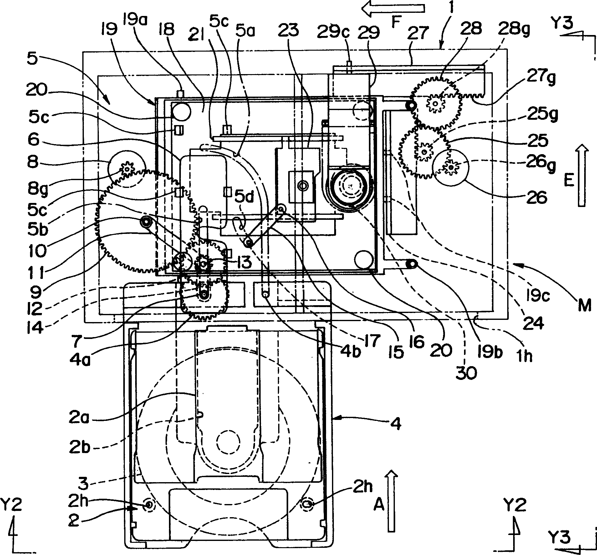
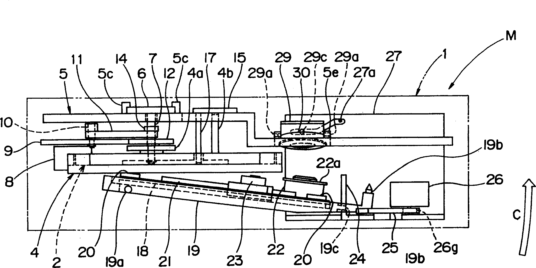
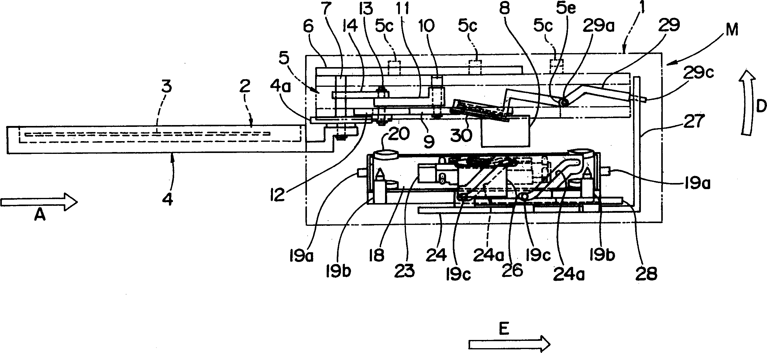
[0041] figure 1 It is an explanatory plan view showing a state in which the tray of the disk drive according to the present embodiment is pulled out. figure 2 is an explanatory front view of the above-mentioned disk device, and is obtained from figure 1 View in the direction of the Y2-Y2 arrow. also, image 3 is a side explanatory view of the above-mentioned disk device, from figure 1 View in the direction of the Y3-Y3 arrow. in addition, Figure 4 It is an explanatory plan view showing an enlarged main part of the disk transfer mechanism of the above-mentioned disk device.

[0042] As shown in the above-mentioned figures, the disk drive M according to this embodiment has a main body case 1 (casing) whose overall shape is substantially rectangular parallelepiped, and a disk tray 4 (hereinafter referred to as abbreviated as appropriate). for "brackets")...


PUM


Abstract

A disk conveying device provided in a disk apparatus, for conveying a disk between a first position outside of the disk apparatus and a second position inside of the disk apparatus, includes a swivel mechanism for swiveling the disk by 90 degrees substantially within a plane substantially parallel to the recording surface of the disk, at least in part of the conveying route between the first position and second position, thereby the disk conveying device is capable of shortening straight stroke of loading and unloading of disk and reducing the depth size of disk apparatus to realize a compact design.

Description

technical field [0001] The present invention relates to a disc transport device for transporting an information recording medium between a first position outside the disc unit and a second position inside the disc unit, and a disc unit having the disc transport unit. Background technique [0002] In the past, as a disk device for recording and / or reproducing information signals on a disk as an information recording medium, generally, a disk pick-and-place position (first position) outside the disk device and a recording / reproducing position inside the disk device have been known. (Second position) A disk device that transfers the above-mentioned disk between. [0003] In addition, in this specification, "recording and / or reproduction" means "at least one of recording and reproduction", and it is a simplified representation. In addition, the term "disc" includes not only "a single disc = a so-called bare disc" but also a "cartridge disc" stored in a cartridge (cartridge). "...

Claims


Application Information

Patent Timeline
Patent Type & Authority Applications(China)
IPC IPC(8): G11B17/028G11B17/04
CPCG11B17/0288G11B17/056
Inventor 丸山益生
Owner PANASONIC CORP
Why Eureka
Try Eureka