Method for mounting radar of vehicle , radar for vehicle use and monitoring method
An installation method and radar technology, applied in vehicle parts, antenna supports/installation devices, measurement devices, etc., can solve problems such as inability to detect and generate dead angles.
- Summary
- Abstract
- Description
- Claims
- Application Information
AI Technical Summary
Problems solved by technology
Method used
Image
Examples
Embodiment approach 1
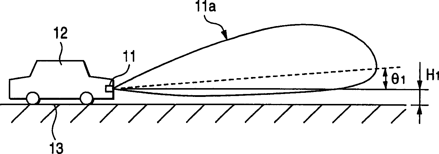
[0036] Hereinafter, a method of mounting a radar for a vehicle and an embodiment of the radar for a vehicle according to the present invention will be described with reference to the drawings. figure 1 It is a side view showing a state in which the vehicle radar 11 according to Embodiment 1 is mounted on a vehicle. The transmitting antenna 14 of the vehicle radar 11 is installed in the bumper of the vehicle 12 [height H from the road surface 13 1 (e.g. 0.5m) position]. In addition, the vehicle radar 11 is installed so that the axis of the directional radiation pattern of the antenna faces upward at an angle θ1 with respect to the horizontal direction. In addition, 11 a in the figure shows a vertical directional radiation pattern of the transmitting antenna 14 of the vehicle radar 11 .
[0037] figure 2 It is a schematic diagram showing a state in which vehicle radar 11 is mounted on vehicle 12 such that the axis of the vertical directional radiation pattern of transmittin...
Embodiment approach 2
[0058] Next, the vehicle radar 11 according to Embodiment 2 will be described. In Embodiment 2, mounting members used when mounting the vehicle radar 11 on the vehicle 12 will be described in detail. In addition, the same components as in Embodiment 1 are denoted by the same reference numerals, and descriptions thereof are omitted.
[0059] FIG. 11 is a side view showing a bracket 100 (mounting member) used when mounting the vehicle radar 11 according to Embodiment 1 to a vehicle 12 . FIG. 11( a ) is a side view of the bracket 100 when the bottom plate 105 of the bracket 100 is brought into contact with a flat surface. FIG. 11( b ) shows the bracket 100 viewed from the direction of arrow XIB in FIG. 11( a ). The bracket 100 has side panels 101 , side panels 102 and a bottom panel 105 . The side plate 101 and the side plate 102 stand substantially vertically from the bottom plate 105 . The side plate 101 and the side plate 102 each have two protruding pieces 103a, 103b prot...
Embodiment approach 3
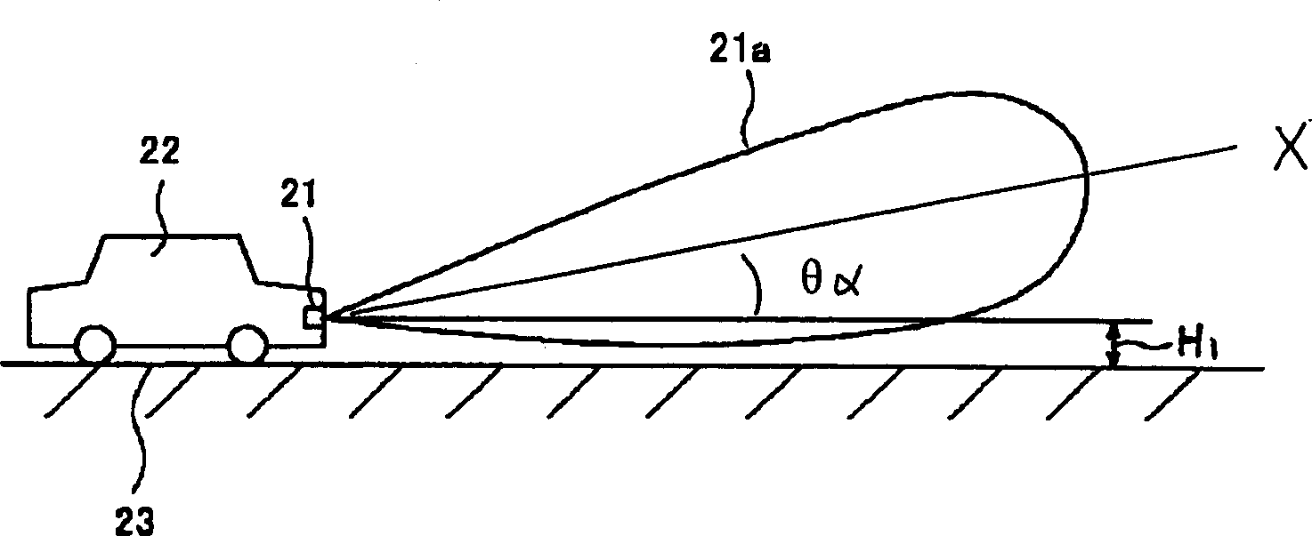
[0068] Next, a vehicle radar according to Embodiment 3 will be described. image 3 It is a schematic diagram showing a state in which vehicle radar 21 is mounted on vehicle 22 such that the normal line of the radio wave emitting surface of vehicle radar 21 in Embodiment 3 is parallel to the horizontal direction of road surface 23 . The transmitting antenna (not shown) of vehicle radar 21 is installed in the bumper of vehicle 22 [from the height H of road surface 23 1 (e.g. 0.5m) position]. In addition, the vehicle radar 21 is configured such that the vertical directional radiation pattern of the antenna is asymmetrical with respect to the directional axis X. As shown in FIG. 21 a in the figure shows the directional radiation pattern in the vertical plane of the antenna of the vehicle radar 21 . An electrical inclination is provided in advance to the transmitting antenna of the vehicle radar 21 . Therefore, the angle between the directional axis X and the horizontal directio...
PUM
 Abstract
Description
Claims
Application Information
 - R&D Engineer
- R&D Manager
- IP Professional
- Industry Leading Data Capabilities
- Powerful AI technology
- Patent DNA Extraction
Browse by: Latest US Patents, China's latest patents, Technical Efficacy Thesaurus, Application Domain, Technology Topic, Popular Technical Reports.
© 2024 PatSnap. All rights reserved.Legal|Privacy policy|Modern Slavery Act Transparency Statement|Sitemap|About US| Contact US: help@patsnap.com


