
Soft switch power converter

一种功率变换器、升压变换器的技术,应用在输出功率的转换装置、交流功率输入变换为直流功率输出、直流功率输入变换为直流功率输出等方向,能够解决很难等问题

Inactive Publication Date: 2005-02-02
DELTA ELECTRONICS INC
View PDF0 Cites 27 Cited by
  • Summary
  • Abstract
  • Description
  • Claims
  • Application Information

AI Technical Summary

Problems solved by technology

In general, passive lossless snubber circuits suffer from increased component count, and it is difficult to work with soft switching of boost switches, which is detrimental to high-density applications requiring high switching frequencies

Method used


Image

  • Soft switch power converter
  • Soft switch power converter
  • Soft switch power converter

Examples


Embodiment Construction

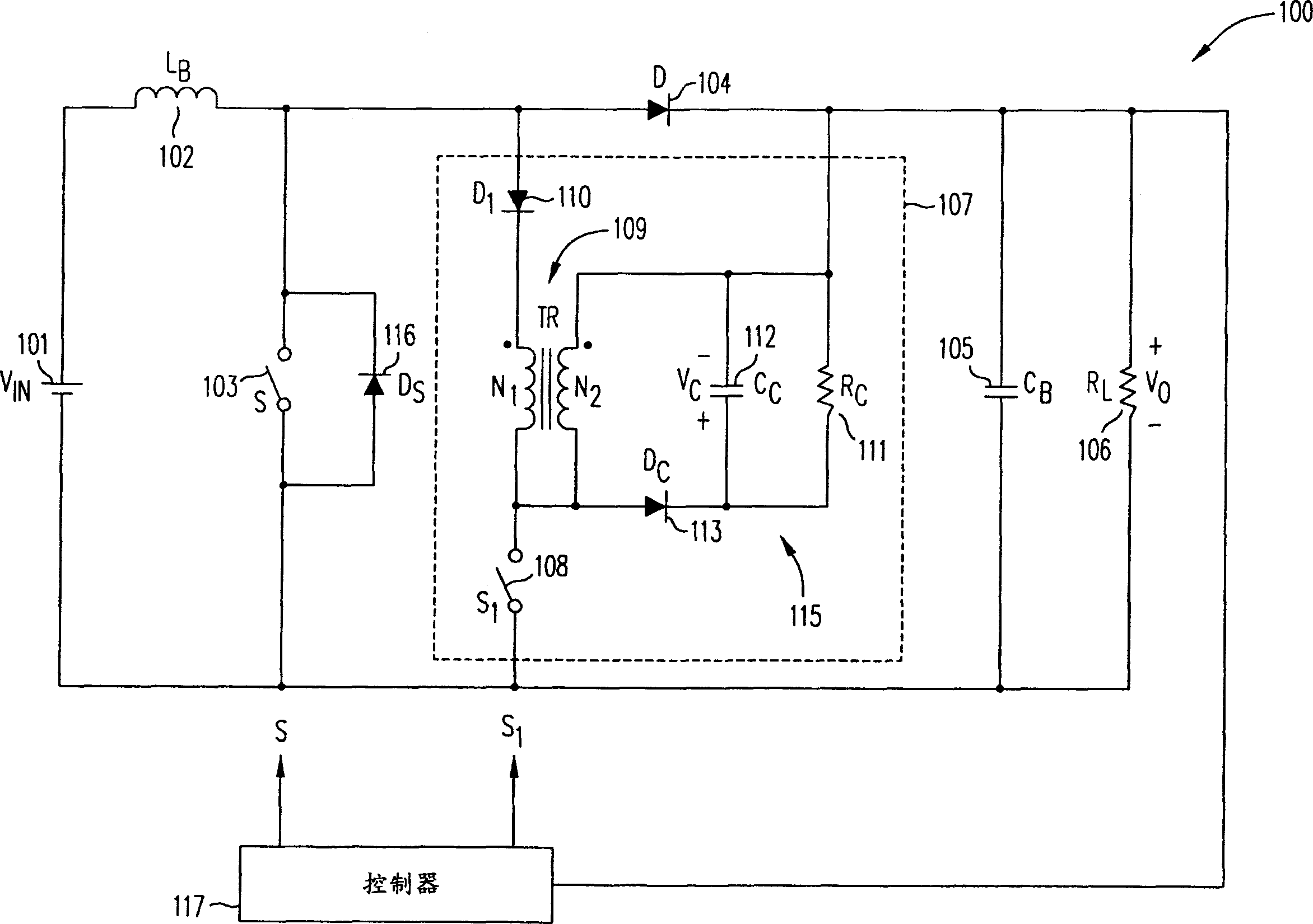
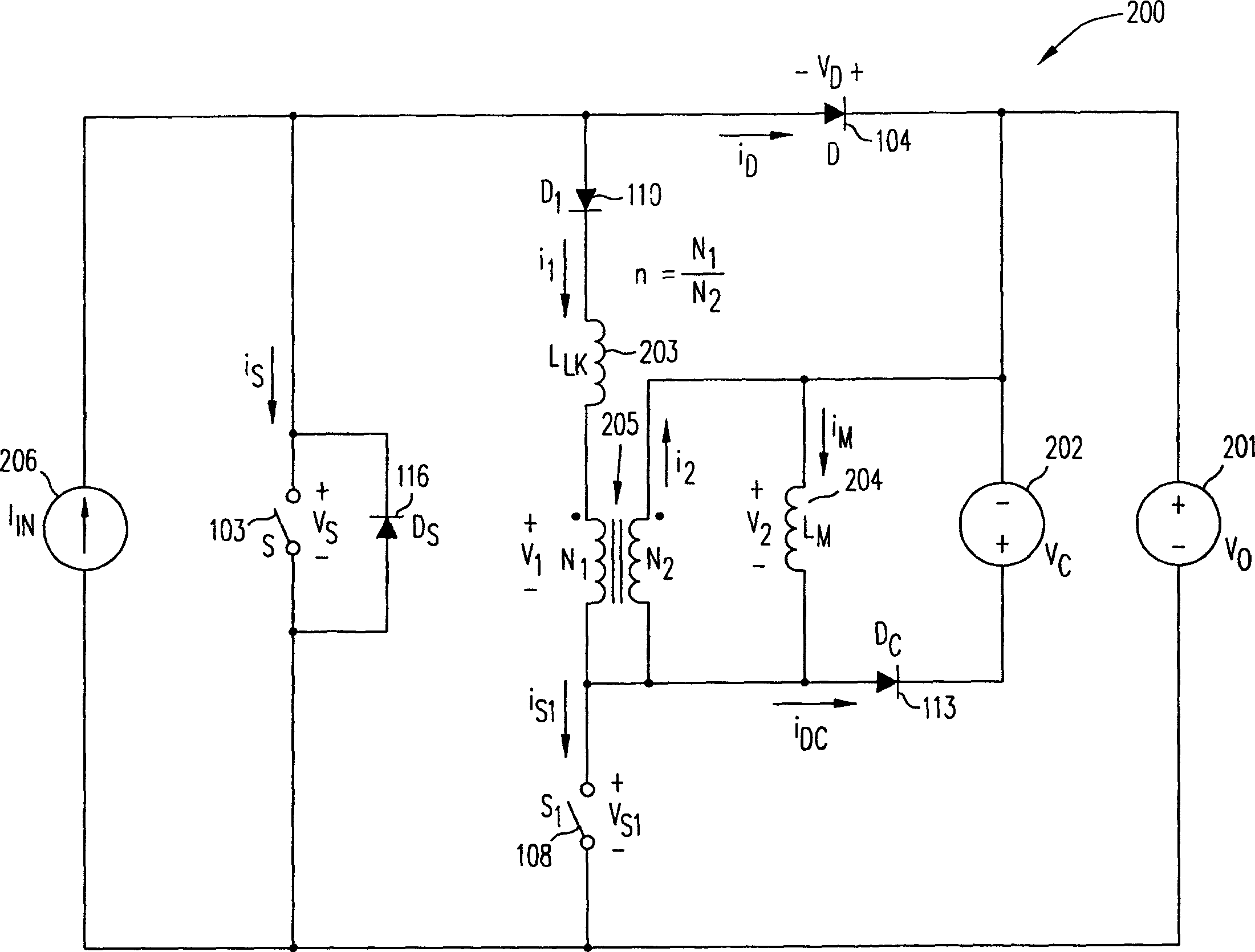
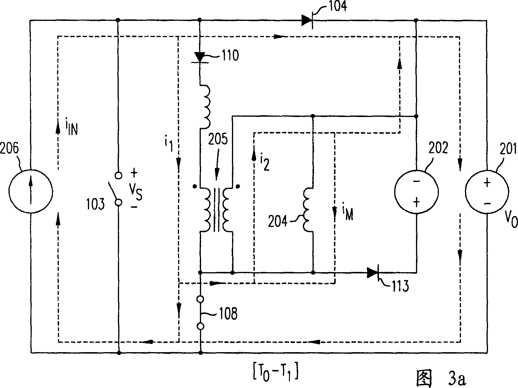
[0035] figure 1 A soft-switching boost circuit 100 according to an embodiment of the present invention is shown. The soft-switching boost circuit 100 includes: providing an input voltage V IN Voltage source 101, boost inductor 102 (inductance value L B ), boost switch 103, boost rectifier 104, energy storage capacitor 105 (capacitance value C B ), load 106 (resistance value R L ) And an active buffer circuit 107 composed of an auxiliary switch 108, a transformer 109, a blocking diode 110, and a resistor 111 (resistance value R C ), clamp capacitor 112 (capacitance value C C ) And a clamping circuit 115 composed of a diode 113. In order to facilitate the explanation of the circuit operation in the soft-switching boost circuit 100, figure 2 A simplified circuit model 200 with voltage and current reference indication directions of the soft-switching boost circuit 100 is provided.

[0036] By assuming the capacitance value C of the energy storage capacitor 105 B And the capacitance v...


PUM


Abstract

A soft-switched boost converter includes an active snubber to provide soft switching of all semiconductor components. Specifically, the current ('turn-off current') in the rectifier is switched off at a controlled rate, the main switch is closed under zero-voltage switching (ZVS) condition, and the auxiliary switch in the active snubber is opened under zero-current switching (ZCS) condition. As a result, switching losses are reduced with beneficial effects on conversion efficiency and EMC performance.

Description

Technical field [0001] The invention relates to a DC / DC and AC / DC power converter. More specifically, the present invention relates to a DC / DC and AC / DC power converter with soft switching in all of its semiconductor components. Background technique [0002] The topology of the boost converter is widely used in various AC / DC and DC / DC converter applications. In fact, boost technology is now mostly used in the front end of DC / DC power supplies with power factor compensation (PFC). The boost topology is also used in a variety of applications that use battery-powered low input voltages to generate high output voltages. At higher power levels, a continuous conduction mode (CCM) boost converter is the preferred topology for a front end with PFC. Therefore, in recent years, a lot of efforts have been made to improve the performance of high-power boost converters. These development efforts are focused on reducing the adverse reverse-recovery characteristics that affect the conversion ef...

Claims


Application Information

Patent Timeline
Patent Type & Authority Applications(China)
IPC IPC(8): H02M1/34H02M3/156H02M3/158H02M3/335H02M7/219
CPCH02M1/34H02M3/156H02M3/1584H02M3/335H02M7/219H02M2001/342H02M2001/344Y02B70/1491H02M1/342H02M1/344Y02B70/10
Inventor 米兰·M·乔瓦诺维克姜云泰张玉明方坤辉
Owner DELTA ELECTRONICS INC
Learn More