Vacuum demand valve

A valve and vacuum chamber technology, applied in the field of vacuum demand valves, which can solve problems such as high cleaning costs and fluid overflow

Inactive Publication Date: 2004-11-17
BAXTER INT INC
View PDF0 Cites 11 Cited by
  • Summary
  • Abstract
  • Description
  • Claims
  • Application Information

AI Technical Summary

Problems solved by technology

For example, a well-known problem is that of fluid spills in industrial environments, where spills of corrosive or hazardous chemicals result in high cleaning costs while placing workers in more dangerous positions

Method used


Image

  • Vacuum demand valve
  • Vacuum demand valve
  • Vacuum demand valve

Examples


Embodiment Construction

[0042] While the invention is capable of embodiments in many different forms, which are shown in the drawings and will be described in detail, the preferred embodiments of the invention, and an understanding of the disclosure, serve as illustrations of the principles of the invention rather than as It is intended to limit the invention in its broader aspects to the illustrated embodiments.

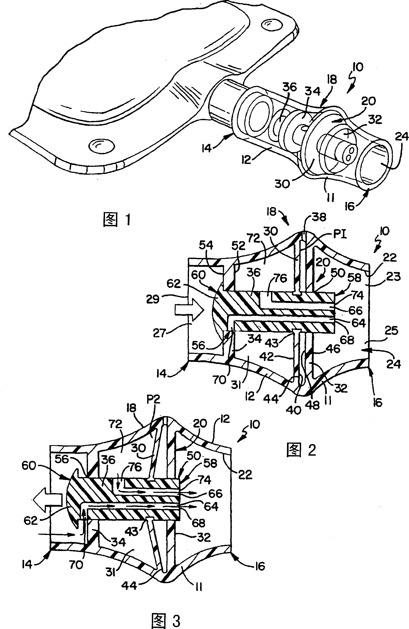
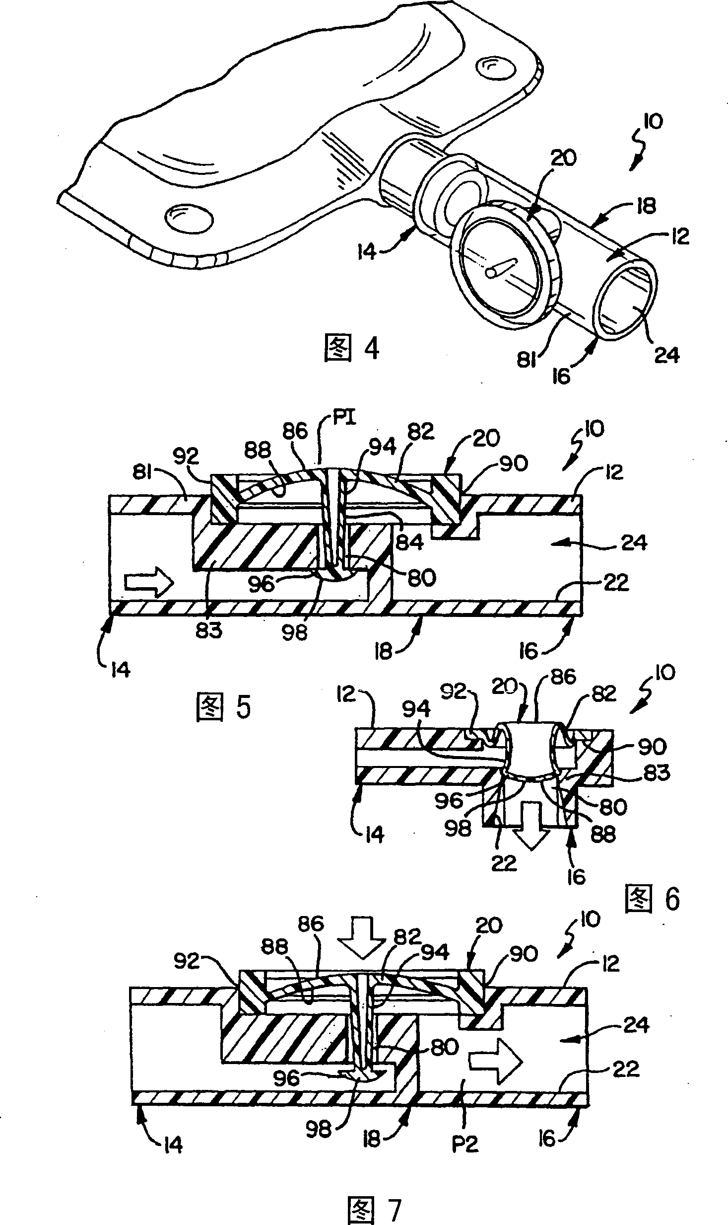
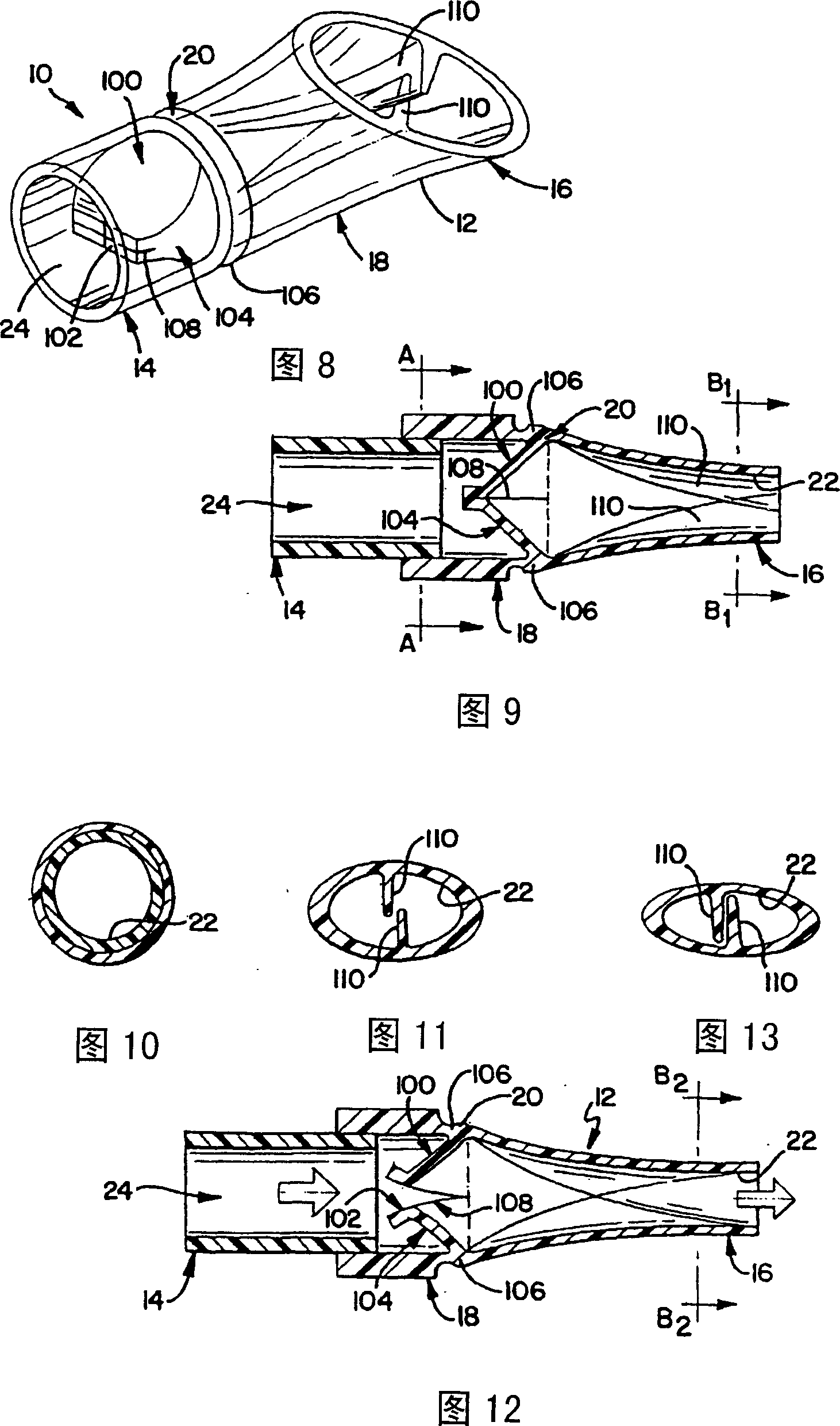
[0043] Referring now initially to Figures 1-26, a vacuum demand valve of the present invention is disclosed, generally indicated at 10 throughout. In a preferred embodiment, valve 10 may be implemented in a tubular structure and may be referred to as tube 10 . In one embodiment, the valve or tube 10 may be a medical tube 10 generally including an elongated sidewall 12 , a proximal end 14 , a distal end 16 , an intermediate section 18 and a valve member 20 . Tube 10 is generally considered to be the housing of the valve. The elongate side wall 12 has an inner wall 22 that defines a channe...


PUM


Abstract

A vacuum demand valve for delivering a flowable material is disclosed. The valve has a housing having a proximal end, a distal end, an intermediate segment therebetween defining a passageway wherein the flowable substance can flow from the proximal end to the distal end. The housing can be a tubing. A valve member is located along the intermediate segment. The valve member has a closed condition wherein the flow of the flowable material from the proximal end to the distal end is stopped and an open condition wherein the flow of the flowable material from the proximal end to the distal end is unstopped. The valve member is biased in the closed condition and is responsive to a partial vacuum provided by the user through the passageway for placing the valve member in the open condition.

Description

technical field [0001] The present invention relates generally to valves for use with fluid containers or pipes, and more particularly, to vacuum demand valves associated with fluid containers or within pipes. Background technique [0002] In the medical field, beneficial agents are often delivered to patients through polymer tubes. When the amount of beneficial agent needs to be tightly controlled, the beneficial agent is typically delivered intravenously through a tube and regulated by a precision pump. In many cases, however, the amount of beneficial agent introduced into the patient's body need not be tightly controlled. In these cases, the beneficial agent is typically introduced orally by the patient. [0003] Oral administration of beneficial agents is also achieved through the polymer tube. To deliver the beneficial agent from the container to the patient, one end of the tube length is contacted with the beneficial agent and the other end of the tube is inserted i...

Claims


Application Information

Patent Timeline
IPC IPC(8): F16K7/12A47G21/18A61J1/05A61J1/10A61J15/00A61M11/06A61M15/00A61M39/00A61M39/22F16K7/17F16K15/02F16K15/03F16K15/14
CPCF16K15/14A61J7/0046A47G21/185A61M2039/244Y10S137/907A61M39/22A61J7/0053A61M2039/242A61J1/10A61M39/24A61M39/227A61J15/00F16K15/147A61M2039/2406A61M2039/2486A61J1/1475Y10T137/789Y10T137/7836Y10T137/7781Y10T137/7882A47G21/183A47G19/2266F16K15/1472F16K15/148
Inventor 马克·E·威廉森斯科特·R·阿里亚尼奥艾伦·W·马蒂拉阿诺德·C·比尔斯泰德保罗·M·迪佩尔纳迈克尔·R·普里斯科戴维·W·彭宁顿阿特夫·M·亚尔德姆哲悉尼·T·施密斯马克·C·佩里马克·贝洛蒂哈尔·C·丹比
Owner BAXTER INT INC
Why Eureka
Try Eureka