
Bidirectional wavelength division multiplexing self recovering ring network

An optical add-drop multiplexer and ring network technology, applied in the field of optical networks, can solve problems such as optical signal interruption, loopback, and data loss

Inactive Publication Date: 2004-07-28
SAMSUNG ELECTRONICS CO LTD
View PDF0 Cites 14 Cited by
  • Summary
  • Abstract
  • Description
  • Claims
  • Application Information

AI Technical Summary

Problems solved by technology

[0010] Another drawback is that the optical signal passing through the normal link is looped back together with the optical signal passing through the failed link
As a result, the transmitted optical signal was interrupted and data loss was suffered

Method used


Image

  • Bidirectional wavelength division multiplexing self recovering ring network
  • Bidirectional wavelength division multiplexing self recovering ring network
  • Bidirectional wavelength division multiplexing self recovering ring network

Examples


Embodiment Construction

[0023] Preferred embodiments of the present invention will be described below with reference to the accompanying drawings, and for purposes of illustration and simplification, detailed descriptions of known functions and configurations included will be omitted since they may obscure the subject matter of the present invention.

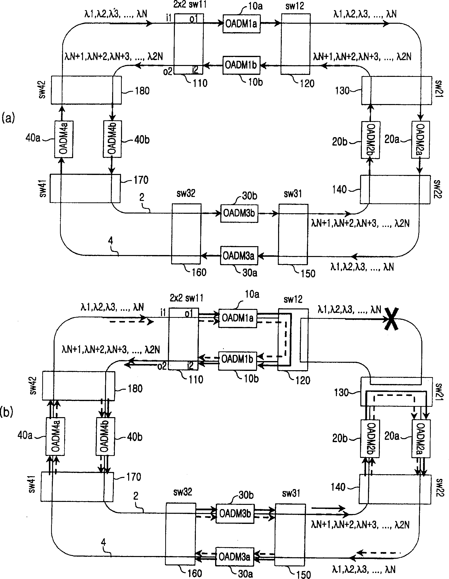
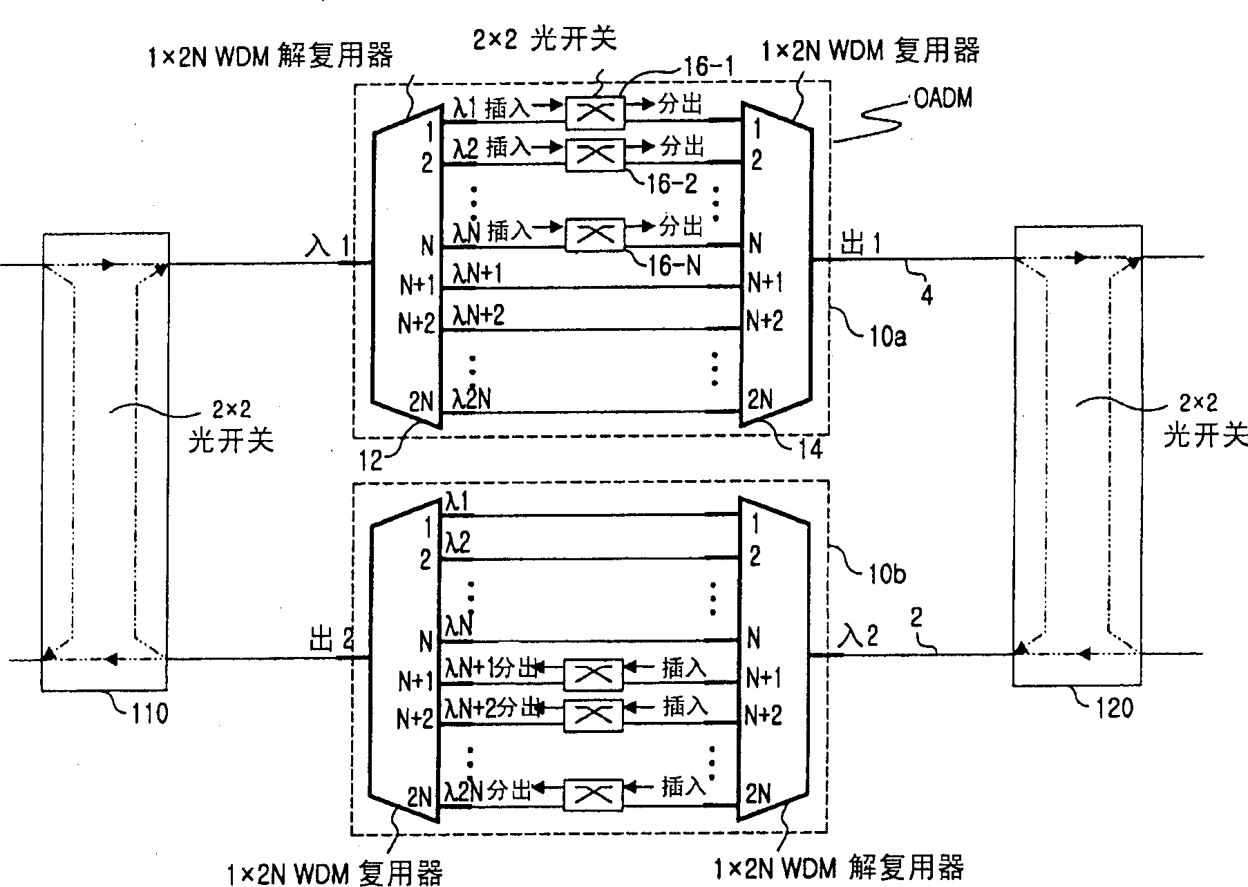
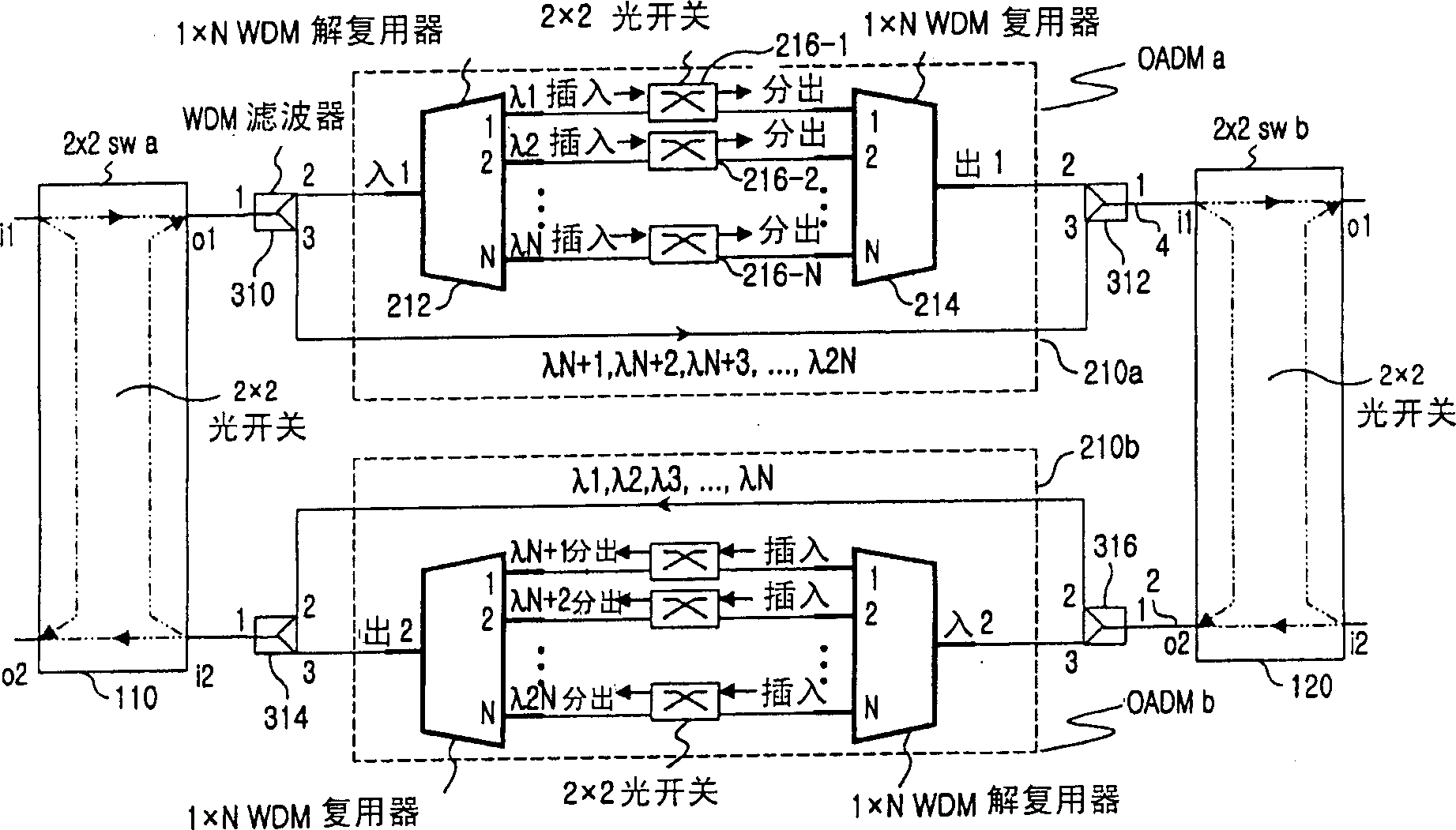
[0024] image 3 It is a schematic diagram showing an optical add / drop multiplexer and a 2×2 optical switching device according to the first embodiment of the present invention. Figure 4 A and 4B are shown using image 3 A schematic diagram of a ring network of an optical add / drop multiplexer and a 2×2 optical switching device according to the first embodiment of the present invention is shown. especially, Figure 4 A denotes a network with transmission links operating in normal mode, Figure 4 In the ring network represented by B, the optical fiber transmission link connecting one optical add-drop multiplexer and another optical add-drop multiplexer ...


PUM


Abstract

A bidirectional WDM self-healing ring network is provided and includes an outer ring network and an inner network for processing N units of optical signals and for performing a protection switching by using the outer ring network when the inner ring network suffers a link failure. Each node of the ring network includes optical add / drop multiplexers positioned in the inner ring network and the outer ring network; a demultiplexer and a multiplexer having a capacity of 1xN, respectively; a pair of switching devices extending through the outer ring network and the inner ring network and is positioned between the optical add / drop devices and an optical fiber link connected to other node; and, a plurality of WDM filters positioned at both ends of the optical add / drop multiplexers, such that when a link failure occurs in the optical fiber link, the WDM filters transfer optical signals processed in the ring network including the WDM filters to one end of the optical add / drop multiplexer connected to the WDM filters, and transfer optical signals processed in the other ring network excluding the WDM filters to a WDM filter connected to the other end of optical add / drop multiplexer, without passing the optical signals through the optical add / drop multiplexer connected to the WDM filters.

Description

technical field [0001] The present invention relates to an optical network, in particular to an optical network using WDM (Wavelength Division Multiplexing) technology. Background technique [0002] Since WDM technology can transmit multiple optical signals through a single strand of optical fiber, it is already possible to transmit multiple very high-speed and large-capacity stored optical signals. With the aid of the exchange of add / drop optical signals in the optical layer, an optical network can be constructed based on WDM technology. [0003] WDM optical networks are generally classified into ring networks using optical add-drop multiplexers and mesh networks using optical cross-connects. The WDM optical network transmits very high-speed mass-stored data through each optical fiber, thus requiring the WDM optical network to efficiently handle any undesired system failures. In the case of a mesh network, nodes of each optical network are connected to each other through ...

Claims


Application Information

Patent Timeline
Patent Type & Authority Applications(China)
IPC IPC(8): H04B10/27H04B10/00H04B10/03H04B10/032H04B10/035H04B10/038H04B10/07H04B10/275H04B17/40H04J14/00H04J14/02H04L12/437
CPCH04J14/0213H04J14/0283H04J14/0212H04J14/0291H04B10/03H04B10/275H04B10/2581
Inventor 金钟权都尚铉吴润济李基喆李钟勋李学弼朴世刚
Owner SAMSUNG ELECTRONICS CO LTD
Learn More