
Telephone control system

A control system and telephone technology, applied in telephone communication, telephone structure, telephone line maintenance circuit, etc., can solve the problem of not being able to know the incoming call

Inactive Publication Date: 2004-05-12
SHARP KK
View PDF3 Cites 3 Cited by
  • Summary
  • Abstract
  • Description
  • Claims
  • Application Information

AI Technical Summary

Problems solved by technology

Adopting the busy state interrupt connection scheme disclosed in JP-A4-172743 and the button telephone set disclosed in JP-A2001-292463, it is possible to connect to other lines without disconnecting the busy line connected to the telephone set, that is, That is to say, it is possible to disconnect multiple lines, but there is a problem: when the telephone set that is occupying the line and holding the call receives an incoming call from another line, it is far away from the telephone set that holds the call. of users have no way of knowing about the new incoming call
[0010] For the master-slave telephone system disclosed in JP-A5-344054, there is a problem that, when paging is performed, for example, in the off-hook (conversation) state of a sub-set, a speaker or a speaker included in the sub-set will be called. Transmits a ring tone in the ring so it can be heard by the other party

Method used


Image

  • Telephone control system
  • Telephone control system
  • Telephone control system

Examples


Embodiment Construction

[0058] Preferred embodiments of the present invention will now be described below with reference to the accompanying drawings.

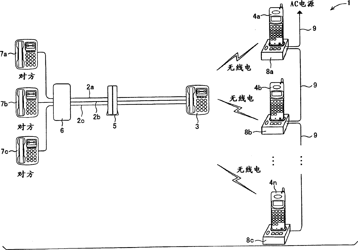
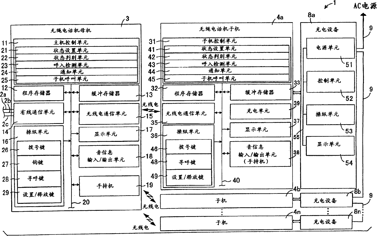
[0059] FIG. 1 is a schematic diagram showing the structure of a telephone control system 1 of an embodiment of the present invention. Telephone control system 1 comprises a main telephone set 3 (hereinafter referred to as " main frame ") and n sub-telephone sets 4a, 4b, ..., 4n (hereinafter referred to as " sub-set "), main frame 3 is connected to three lines 2a, 2b , 2c, n slaves communicate with the host 3 through radio channels on pre-assigned frequencies. In this way, in this embodiment, the sub-units 4a, 4b, . . . , 4n corresponding to the main unit 3 constitute a cordless telephone set.

[0060] The host 3 is connected to a customer premise switchboard 5 (a customer premise switchboard) constituted by a router or a repeater, and it is also connected to the other party's telephone sets 7a, 7b, 7c through the network 6 connected to the customer ...


PUM


Abstract

A parent telephone 3 which constitutes a telephone control system 1 includes a condition setting means 21, a condition sorting means 22, an incoming call detecting means 23, an alarm means 24m, and a parent machine control means 11 for controlling each operation of these means. The parent machine control means 11 causes the report means 24 under control to report the incoming call by at least sound information if one line is determined to be a call held condition through the condition sorting means 22, while a new incoming call signal from another line is detected by the incoming call detecting means 23.If one line is determined to be a call condition through the condition sorting means 22, the alarm means 24 is caused under control to alarm the incoming call by at least visible information.

Description

technical field [0001] The invention relates to a telephone control system. Background technique [0002] In today's age of development of information and communication networks, people talk on the phone more often than writing letters to understand each other. Therefore, such a situation often occurs: that is, an incoming call is superimposed on the busy line connected to the telephone set and is received. In this case, a busy signal is sent to the telephone receiver of the subscriber who was overlapped, so that the subscriber will usually call back after a certain period of time. As a technique for eliminating such inconvenience, an interrupt connection service has been devised. However, for the actual operation of the interrupt connection service, several problems need to be improved. [0003] For example, in the event that a busy phone line has received an incoming call from any other party other than the talking party, the disconnection service will send an incoming ...

Claims


Application Information

Patent Timeline
Patent Type & Authority Applications(China)
IPC IPC(8): H04M1/725H04M3/42H04M1/00H04M1/80H04M3/428H04Q3/58
CPCH04M3/428H04M1/725
Inventor 吉谷典文
Owner SHARP KK
Learn More