Electric wheel chair

An electric wheelchair and chair frame technology, which can be used in patient chairs or special transportation tools, vehicle rescue, medical transportation, etc., can solve problems such as high cost, difficult maintenance, and inability to easily control with both hands.

Inactive Publication Date: 2003-07-09
KARMA MEDICAL PRODUCTS CO LTD
View PDF0 Cites 16 Cited by
  • Summary
  • Abstract
  • Description
  • Claims
  • Application Information

AI Technical Summary

Problems solved by technology

[0002] Early electric wheelchairs were designed to use the speed coordination between the two motors to achieve the purpose of traveling and turning. This type of electric wheelchair has a complex structure, high cost, and difficult maintenance. Therefore, the applicant of the present invention has made improvements to the above deficiencies. design a figure 1 , 2 As shown in the electric wheelchair, the electric wheelchair 1 mainly includes: a base 11, a power mechanism 12, a differential mechanism 13, a control mechanism 14 and a steering mechanism 15, wherein the base 11 is at the bottom of a chair frame 111 Four wheels 112 are installed, and an intubation base 113 is set at a position on one side of the chair frame 111, and the power mechanism 12 is installed on the base 11 to provide the power for the electric wheelchair 1 to move. The differential mechanism 13 is It is used to control the rotational speed difference of the rear two wheels 112, and the control mechanism 14 has a linkage rod 141 inserted on the intubation base 113, a hand wheel 142 located at the top of the linkage rod 141, a power mechanism that can start 12 of the control seat 143 and a swing seat 144 installed on the bottom end of the linkage rod 141, wherein the swing seat 144 has a swing plate 145, and the steering mechanism 15 is erected between the front two wheels 112, and with the swing seat 144 The swinging piece 145 moves in unison to control the direction of travel of the electric wheelchair 1
[0003] Although the design of the aforementioned existing electric wheelchair 1 using mechanical means to control the steering can reduce production costs and is also very convenient in maintenance, but in design, because the handwheel 142 of the control mechanism 14 must be erected on one side of the base 11, although the design The installation position of the control mechanism 14 can be changed to meet the needs of customers, but the position of the handwheel 142 for the user to control is fixed after installation, and the user must use a specific hand to control it, which cannot be easily controlled with both hands. This is the electric wheelchair 1 Bad design

Method used


Image

  • Electric wheel chair
  • Electric wheel chair
  • Electric wheel chair

Examples


Embodiment Construction

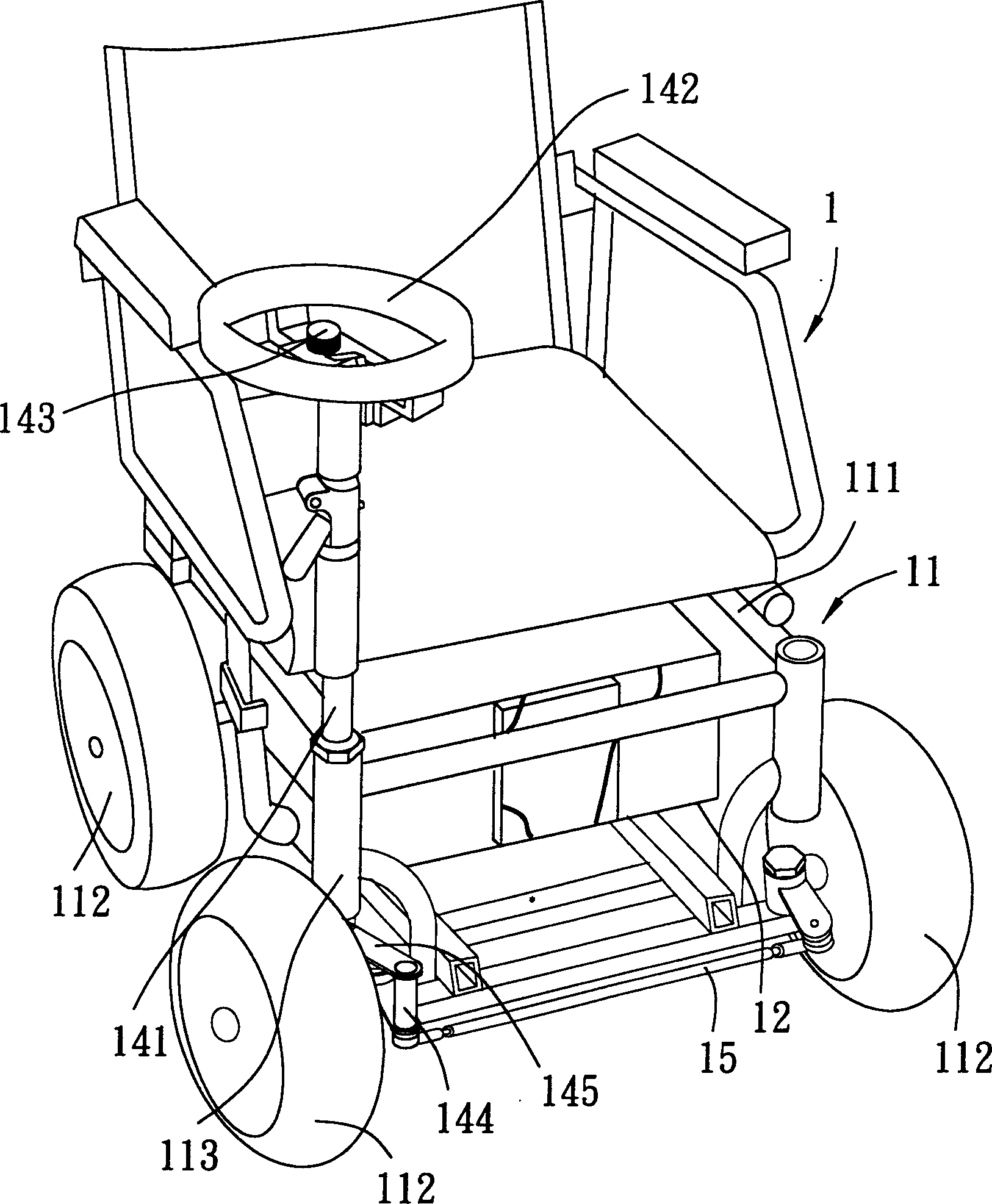
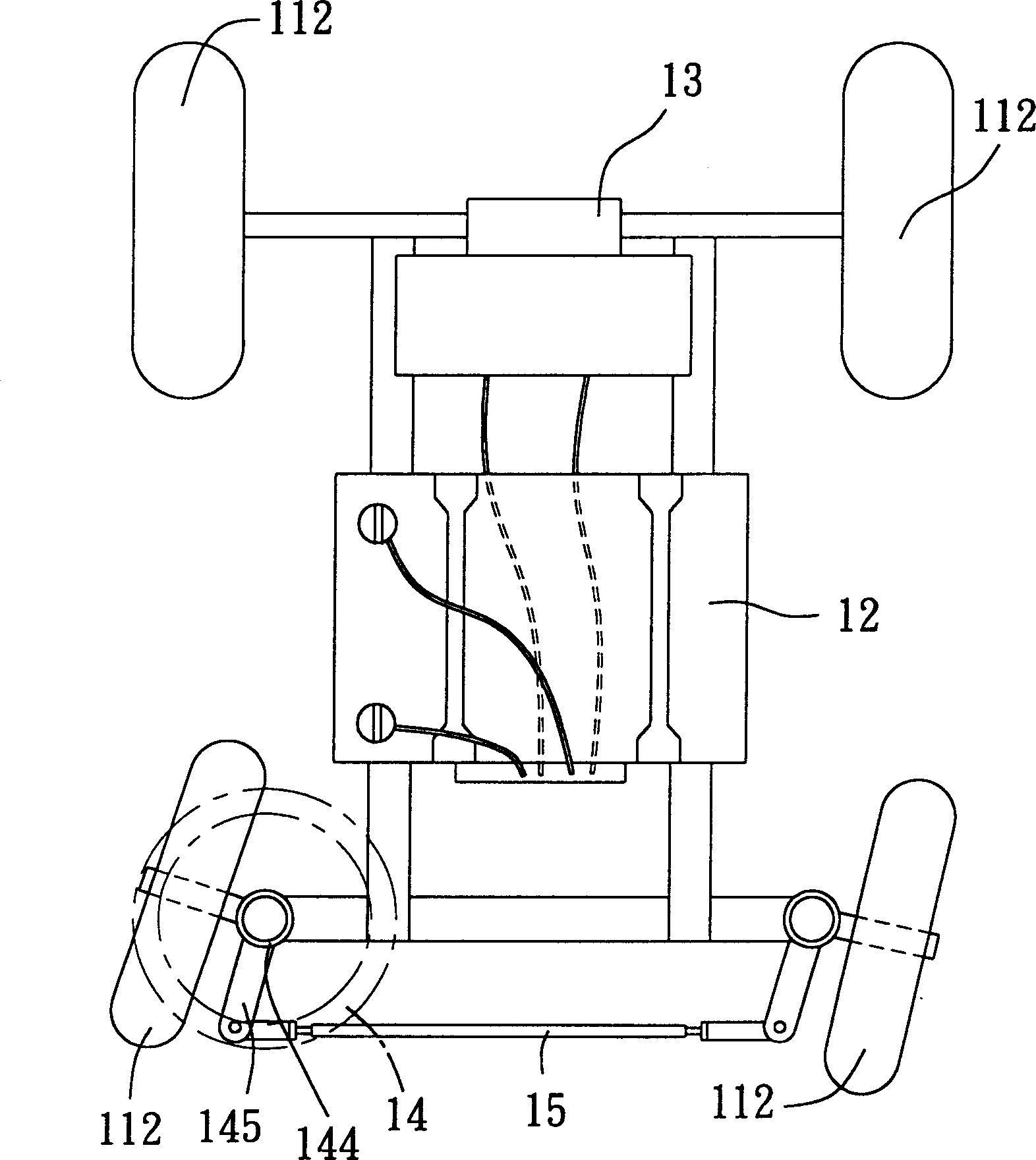
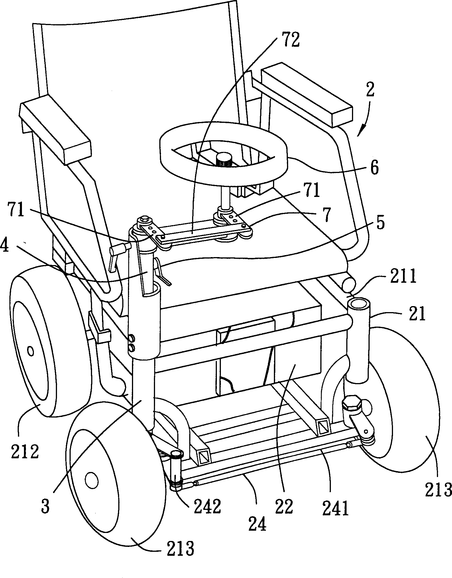
[0021] refer to image 3 , 4 , as shown in the figure, the electric wheelchair 2 of the present invention has a base 21, a power mechanism 22, a differential mechanism 23, a steering mechanism 24, a support mechanism 3, a rotating shaft 4, a positioning mechanism 5, and a control mechanism 6 and a linkage mechanism 7, wherein the base 21 has a chair frame 211, two rear wheels 212 installed at the rear of the chair frame 211, two front wheels 213 installed at the front of the chair frame 211, and the power mechanism 22 has a The storage battery 221 on the chair frame 211, and a motor 222 that accepts the power of the storage battery 221, the differential mechanism 23 is used to connect the motor 222 and the two rear wheels 212, so as to control the speed difference of the rear wheels 212, and the steering mechanism 24 is installed on the two rear wheels. Between the front wheels 213, there is a first connecting rod 241 located in front of the chair frame 211, and two steering ...


PUM


Abstract

The electric wheel chair includes a base seat, on said base seat, a power mechansm, a differential mechanism for regulating rotating speed difference and a steering mechanism. In order to do not affect convenience for incoming and outcoming, at the same time of making user utilize two hands to operate and control a supporting mechansm is mounted on one side of the base seat, the interior of the supporting mechanism is equipped with a turning shaft coupled with steering mechanism, an operation-control mechanism is mounted on the turning shaft, and a cycloidal seat of said operation-control mechanism has a pivot point and a cycloidal portion which are space and arranged, said pivot point portion is mounted on the turning shaft, and on the cycloidal portion a hand wheel which is coupled with turning shaft by means of coupling mechanism is assembled, said hand wheel can be turned to side of base seat.

Description

【Technical field】 [0001] The invention relates to an electric wheelchair, in particular to an electric wheelchair conveniently controlled by both hands. 【Background technique】 [0002] Early electric wheelchairs were designed to use the speed coordination between the two motors to achieve the purpose of traveling and turning. This type of electric wheelchair has a complex structure, high cost, and difficult maintenance. Therefore, the applicant of the present invention has made improvements to the above deficiencies. design a figure 1 , 2 As shown in the electric wheelchair, the electric wheelchair 1 mainly includes: a base 11, a power mechanism 12, a differential mechanism 13, a control mechanism 14 and a steering mechanism 15, wherein the base 11 is at the bottom of a chair frame 111 Four wheels 112 are installed, and an intubation base 113 is set at a position on one side of the chair frame 111, and the power mechanism 12 is installed on the base 11 to provide the power...

Claims


Application Information

Patent Timeline
Patent Type & Authority Applications(China)
IPC IPC(8): A61G5/04A61G5/10
Inventor 萧顺益
Owner KARMA MEDICAL PRODUCTS CO LTD
Why Eureka
Try Eureka