Driving gear of manipulator

A driving device and manipulator technology, which is applied in the direction of manipulators, program-controlled manipulators, conveyor objects, etc., and can solve problems such as the rise of the substrate path line and the difficult application of dual-arm robots

Inactive Publication Date: 2002-12-04
AKG ACOUSTICS
View PDF0 Cites 31 Cited by
  • Summary
  • Abstract
  • Description
  • Claims
  • Application Information

AI Technical Summary

Problems solved by technology

[0004] However, the former has the problem of enlarging the trajectory of the manipulator (nominal rotation range of the robot), and the latter has the problem of raising the board path line (passline)
What's more, both are difficult to apply on dual-arm robots

Method used


Image

  • Driving gear of manipulator
  • Driving gear of manipulator
  • Driving gear of manipulator

Examples


Embodiment Construction

[0027] Next, embodiments of the present invention will be described with reference to the drawings.

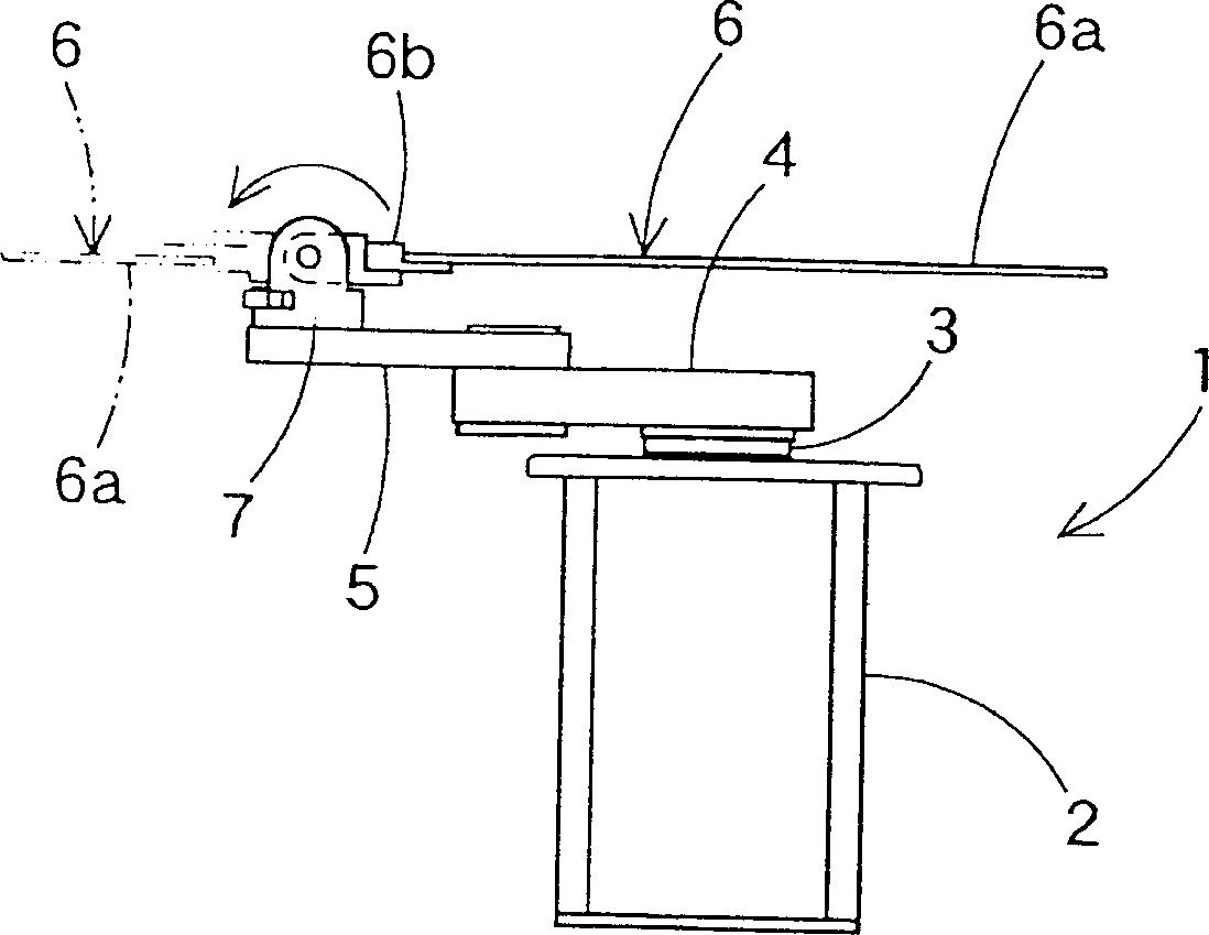
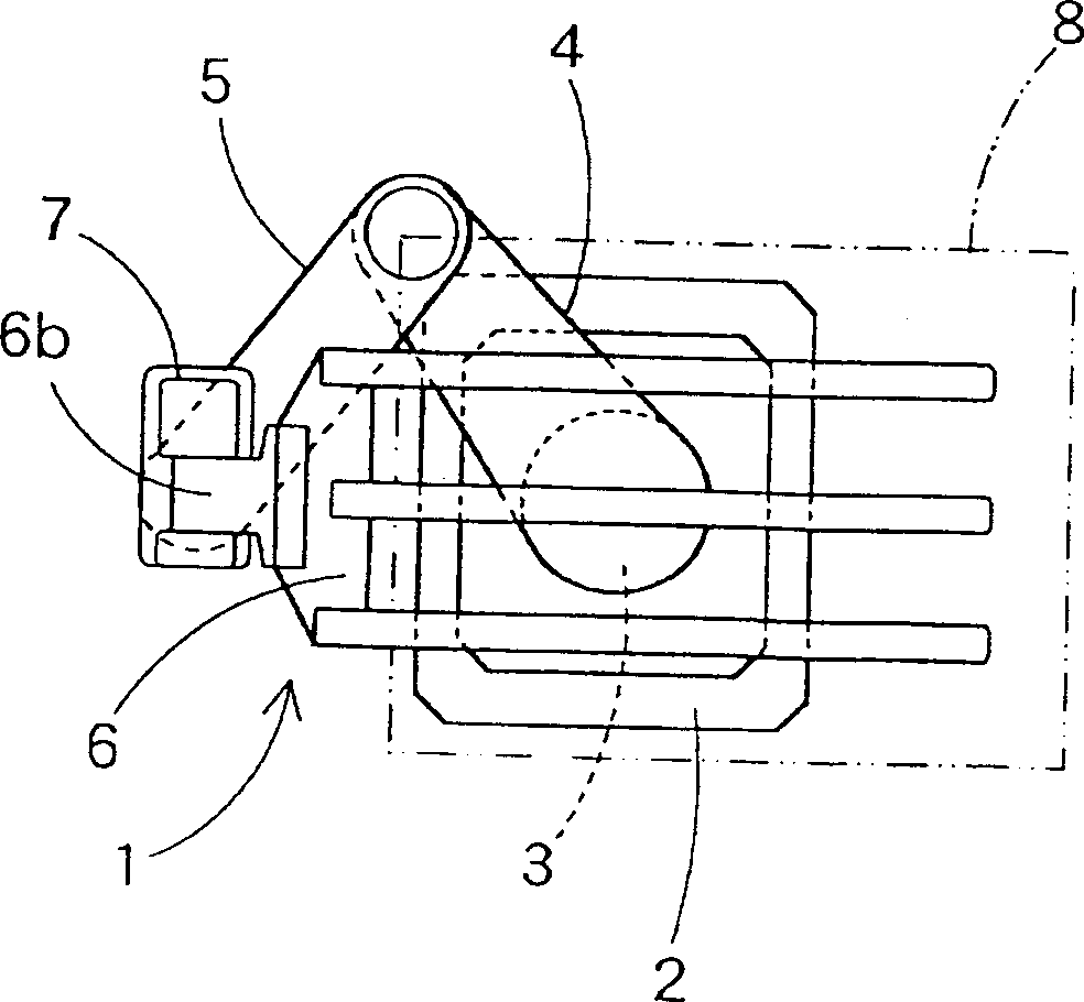
[0028] figure 1 It is a side view of a single-arm scalar robot equipped with a driving device of a manipulator related to an embodiment, figure 2 is the planar graph of the scalar robot, image 3 is the front view of the scalar robot.

[0029] Figure 1 ~ Figure 3 Among them, the scalar robot 1 includes: a base 2 , a body 3 , a second arm 4 , a first arm 5 , a manipulator 6 , and a turning mechanism 7 for the manipulator 6 .

[0030] The manipulator 6 is the same as the manipulator of the existing known scalar robot. It lifts and rotates based on the lifting action and the rotating action of the fuselage 3, and moves on the horizontal plane through the stretching and bending actions of the second arm 4 and the first arm 5. Move on a straight track. In this embodiment, the manipulator 6 is a vacuum suction type, figure 1 The upper face 6a side of the manipulator 6 indi...


PUM


Abstract

PURPOSE: To minimize a footprint when a hand is reversed, to prevent a rise of circuit board path line and furthermore to enable easy application even to a double-arm robot. CONSTITUTION: A driving device of robot hand 6 is the driving device for a movable robot hand 6 that holds a thin circuit board (glass circuit board 8) and has a reversing mechanism 7 that rotates the robot hand 6 around the horizontal axis 9 that is orthogonal with the hand longitudinal direction.

Description

technical field [0001] The present invention relates to a driving device for a robot arm, and more specifically, to a driving device for a robot arm capable of holding and moving thin substrates such as semiconductor wafers, liquid crystal displays, and glass substrates for plasma displays. Background technique [0002] Among existing scalar robots and other robots that have a hand that can hold and move thin substrates, such as Figure 17 Robots of the type shown are provided with a tilting mechanism 32 for rotating the manipulator 6 on a horizontal axis 31 coincident with the longitudinal direction of the manipulator. [0003] And, the robot that existing turnover mechanism 32 is housed, by such as Figure 17 As shown, the manipulator 6 is turned over in the state where the arms 4, 5 are stretched forward, or by Figure 18 As shown, the manipulator 6 is set at a high position sufficiently separated from the first arm 5 to avoid interference between the thin substrate 8 and...

Claims


Application Information

Patent Timeline
Patent Type & Authority Applications(China)
IPC IPC(8): B25J17/02B25J9/06B25J15/00B65G49/06B65G49/07H01L21/677H01L21/68H05K13/00
CPCB25J9/1641B25J17/0241B65G49/063
Inventor 木全一夫中森孝雄加藤克彦中野清宪
Owner AKG ACOUSTICS
Why Eureka
Try Eureka