
Shoe tree of multi-component

A multi-component, shoe last technology, applied in shoe lasts, footwear, applications, etc., to avoid work delays

Inactive Publication Date: 2006-07-26
FAGUS GRECON GRETEN GMBH & CO KG
View PDF0 Cites 0 Cited by
  • Summary
  • Abstract
  • Description
  • Claims
  • Application Information

AI Technical Summary

Problems solved by technology

It can also cause problems when using a dehairing device that gives different degrees of dehairing to various parts of the shoe as it moves into a partially closed last
In such cases, it has the disadvantage that the roughened part is visible even after injecting the sole, since it is not covered by the sole

Method used


Image

  • Shoe tree of multi-component
  • Shoe tree of multi-component
  • Shoe tree of multi-component

Examples


Embodiment Construction

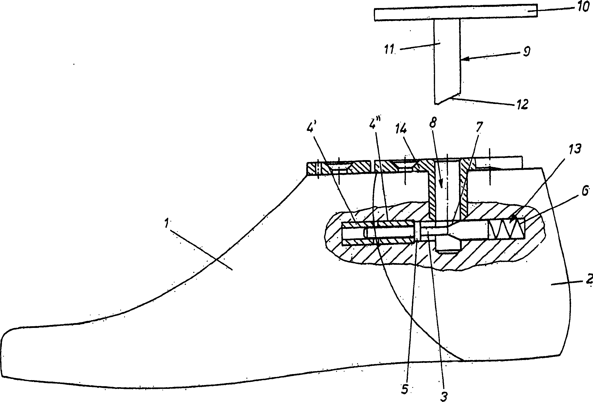
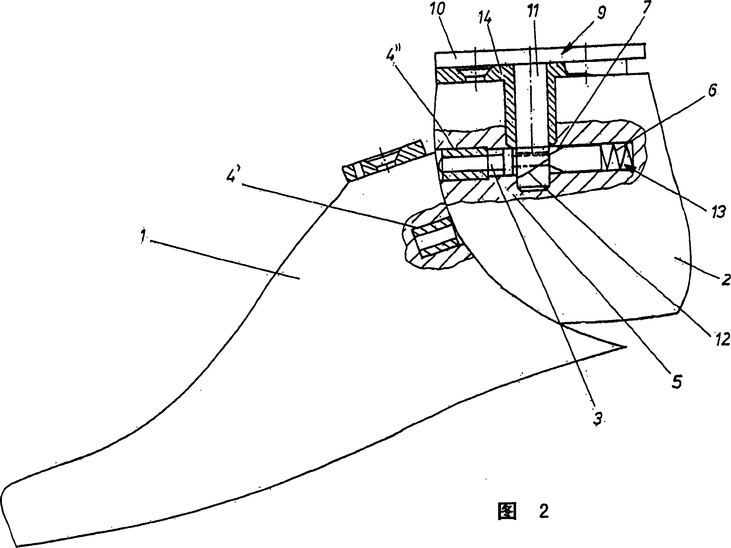
[0028] The shoe last in the embodiment is made up of two parts 1, 2, and they can move relatively. exist figure 1 and 2 and Figure 5 and 6 examples, part 1 can be obtained from figure 1 and 5 The closed configuration of the last shown in Fig. 2 and 6 is moved into the open configuration shown in Figs. This is part 1 of the last.

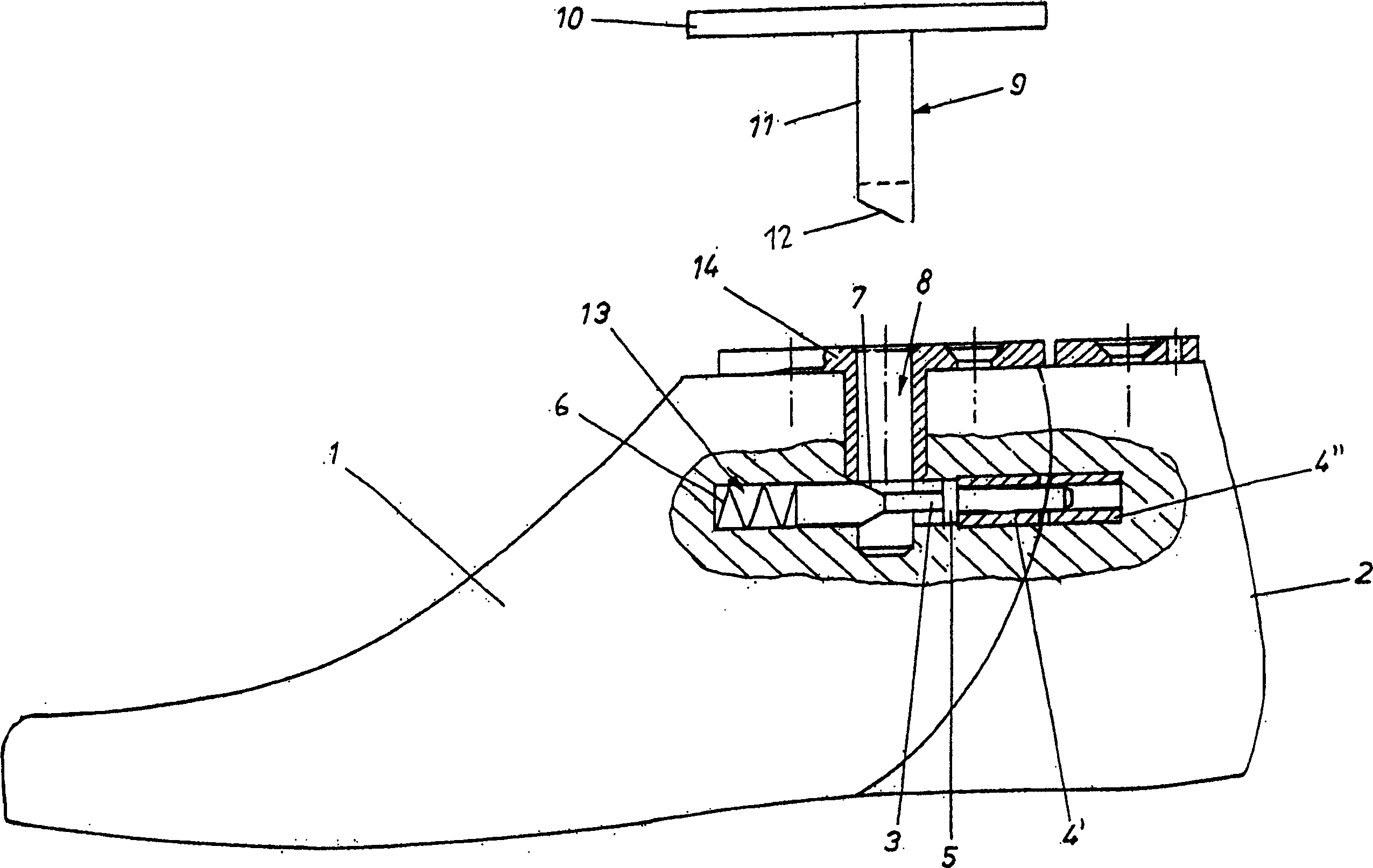
[0029] exist image 3 and 4 In the shoe last, it refers to the part 2 of the shoe last, which can be deflected from the image 3 The closed structure of the last shown in the move to Figure 4 in the open structure shown in .

[0030] The two components 1, 2 are combined together through a connecting mechanism not shown in the figure.

[0031] In order to make parts 1 and 2 of the shoe last in figure 1 , 3 The closed working position of the shoe last shown in 5 is relatively fixed, and a fixing mechanism is provided. The fastening means comprises, as a stop, a pin 3 which is situated in a receiving groove 13 and which is seated in sectio...


PUM


Abstract

The cobblers last has two sections (1,2) with a fixing allowing the sections to move between extended and retracted positions, with the extended position being the working position. The fixing has a stop pin (3) which is adjustable to vary the spacing. The adjuster surfaces (7,12) can be angled. The stop can have a spring (6) to prevent retraction.

Description

technical field [0001] The invention relates to a multi-part shoe last, the parts of which can be moved relative to each other from an operating position to shorten the length of the last, the parts being brought together by a connecting structure. Background technique [0002] These lasts are used in the processing of shoes. They are used in particular to catch the upper or upper of the shoe when it is being soled. [0003] Attaching the sole to the rest of the shoe, for example by gluing. As a way to properly place the sole, for example, the sole is directly injected with PU material. [0004] In order to manufacture a shoe, it is necessary to bring the parts of the last into their working position, for example during injection of the sole. For example, the two parts of the last are aligned in the operating position such that the last has no gaps on its surface. [0005] Known shoe lasts ensure the alignment of the last parts by means of a connecting mechanism which, f...

Claims


Application Information

Patent Timeline
Patent Type & Authority Patents(China)
IPC IPC(8): A43D3/14A43D3/02
CPCA43D3/024
Inventor U・列格伯
Owner FAGUS GRECON GRETEN GMBH & CO KG
Learn More