
Hydrostatic bearing

A hydrostatic bearing, hydrostatic technology, applied in the direction of hydrostatic bearing, bearing, shaft and bearing, etc., can solve the problem that there is no hemispherical surface for reliable lubrication and self-alignment cannot be ensured

Inactive Publication Date: 2004-08-04
TOSHIBA MASCH CO LTD
View PDF0 Cites 1 Cited by
  • Summary
  • Abstract
  • Description
  • Claims
  • Application Information

AI Technical Summary

Problems solved by technology

However, this method requires an additional hydraulic chamber between the bearing pad and the bearing seat
[0006] Moreover, in order to perform self-centering smoothly, in addition to anti-erosion measures, the hemispherical surface of the spherical support mechanism must be sufficiently lubricated, but the existing device does not provide reliable lubrication for the hemispherical surface, so that smooth self-centering cannot be ensured

Method used


Image

  • Hydrostatic bearing
  • Hydrostatic bearing
  • Hydrostatic bearing

Examples


Embodiment Construction

[0031] Embodiments of the present invention will be described in detail below in conjunction with the accompanying drawings. The same components are denoted by the same reference numerals.

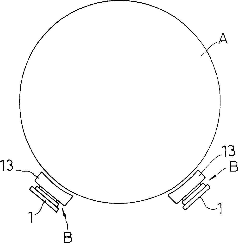
[0032] Fig. 1 schematically shows a hydrostatic bearing according to an embodiment of the present invention used as a radial bearing. In Fig. 1, A denotes a shaft to be supported, and B denotes a hydrostatic bearing device, which supports the shaft A rotatably in pairs. The pair of static pressure bearing devices B are obliquely placed on the left and right sides below the axis A.

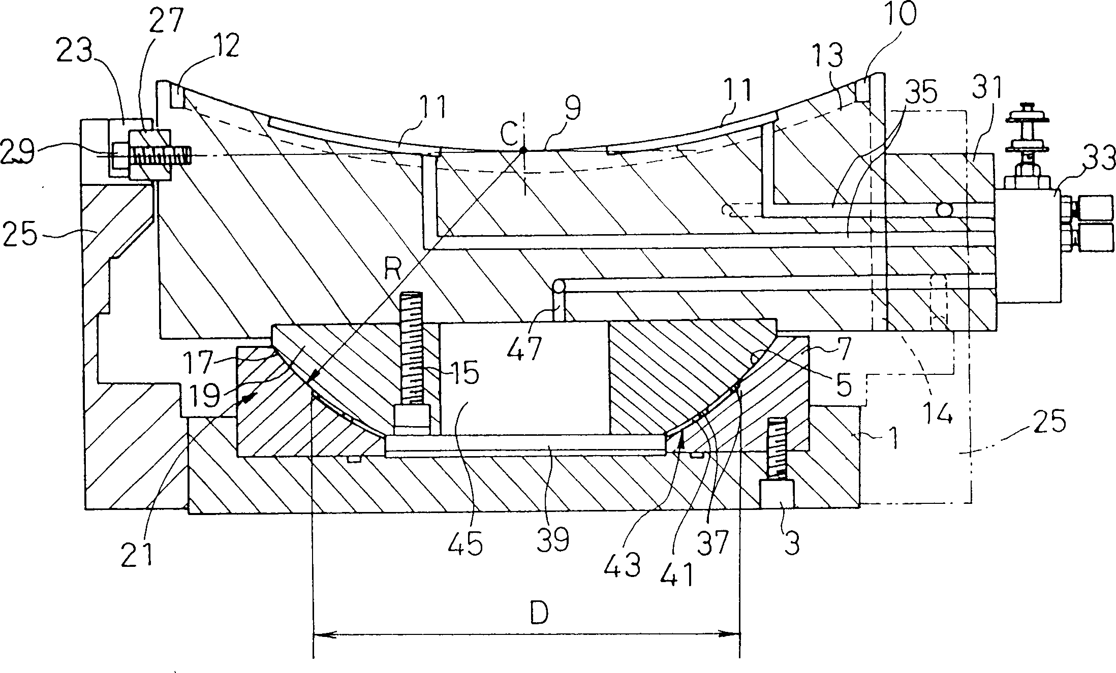
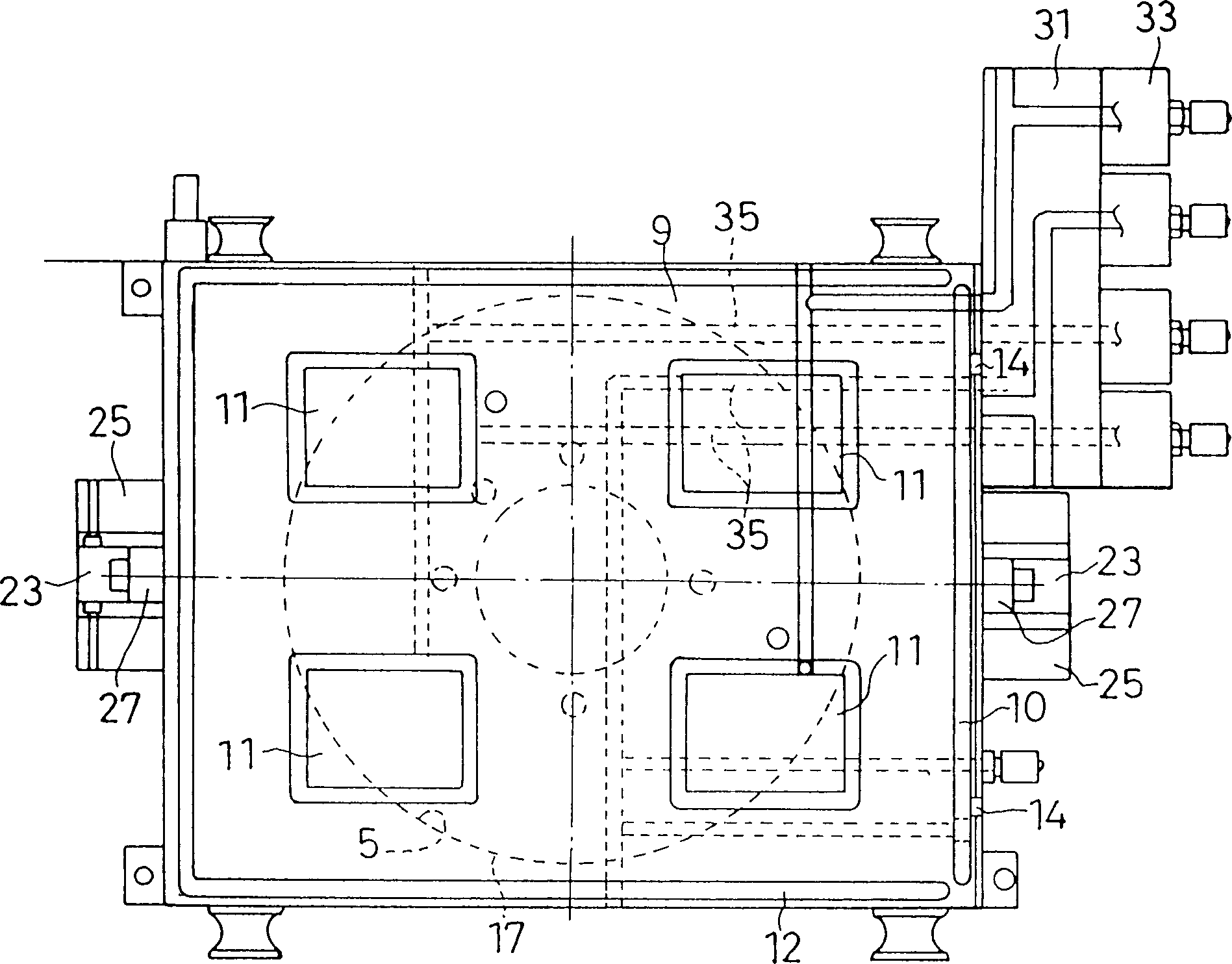
[0033] 2, 3 and 4 are a longitudinal sectional view, a top view and a side view of the hydrostatic bearing device B, respectively. The device B includes: a substantially flat bearing seat 1; a concave spherical lower (supporting) support member 7, the top surface of which is basically a hemispherical or hemispherical annular spherical surface 5, and a bolt (in this figure) Table 3) fastened to the concave to...


PUM


Abstract

In a hydrostatic bearing device having the self-alignment function, a hydrostatic bearing pad 13 is supported by a spherical bearing seat 21 so as to change the working posture by a bearing base 1, and an oil introducing space 43 is provided between semi-spherical surfaces 5, 17 opposite to each other on the spherical bearing seat 21 to feed the pressure oil from a pressure oil passage 47 to the oil introducing space 43. By making effective use of the structure specific to the hydrostatic bearing device having the self-alignment function, the load applied to a spherical bearing seat can be reduced and the spherical bearing seat can be lubricated sufficiently without complicating the structure.

Description

technical field [0001] This invention relates generally to hydrostatic bearing assemblies, and more particularly to hydrostatic bearing assemblies which are self-centering with a spherical support mechanism. Background technique [0002] In large machinery, equipment or components having a rotating part such as a shaft, a hydrostatic bearing arrangement is usually used to support the rotating part with a number of independently working hydrostatic bearing pads (bearing pads) arranged along the rotating periphery. As such a bearing device, there is known a hydrostatic bearing device in which a hydrostatic bearing pad having a hydrostatic oil pocket thereon is supported by a corresponding spherical support mechanism so that the working position can be changed relative to a bearing housing, whereby the The spherical support mechanism realizes self-centering. [0003] The self-centering function is used to automatically compensate the working position of the hydrostatic bearing...

Claims


Application Information

Patent Timeline
Patent Type & Authority Patents(China)
IPC IPC(8): F16C23/04F16C32/06
CPCF16C23/04F16C32/0644F16C32/0655F16C32/0659F16C32/0666F16C32/067
Inventor 羽山定治落合明林英树本多孝政
Owner TOSHIBA MASCH CO LTD
Learn More