
Self-floating rural ecological landscape plant planting device

A technology of ecological landscape and planting device, which is applied in the field of ecological landscape of greening projects, can solve the problems of inconvenient control of the number of floating blocks and buoyancy, inconvenient easy disassembly of the shell, etc., and achieve the effect of simple disassembly and assembly

Pending Publication Date: 2022-08-09
江苏景古规划设计研究有限公司
View PDF0 Cites 2 Cited by
  • Summary
  • Abstract
  • Description
  • Claims
  • Application Information

AI Technical Summary

Problems solved by technology

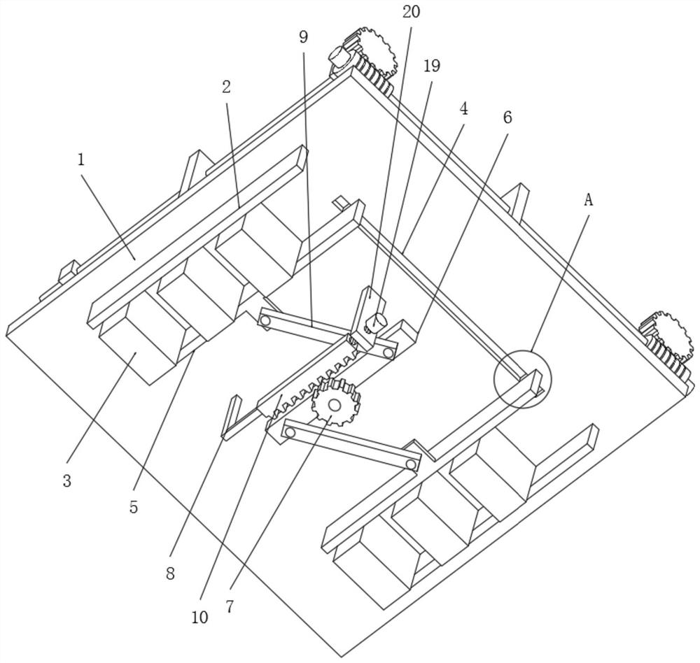
[0005] Aiming at the deficiencies of the prior art, the present invention provides a self-floating rural ecological landscape plant planting device, which solves the inconvenience of the existing self-floating rural ecological landscape plant planting device to control the number and buoyancy of floating blocks and the inconvenience of The problem of easy disassembly of the shell

Method used


Image

  • Self-floating rural ecological landscape plant planting device
  • Self-floating rural ecological landscape plant planting device
  • Self-floating rural ecological landscape plant planting device

Examples


Embodiment 1

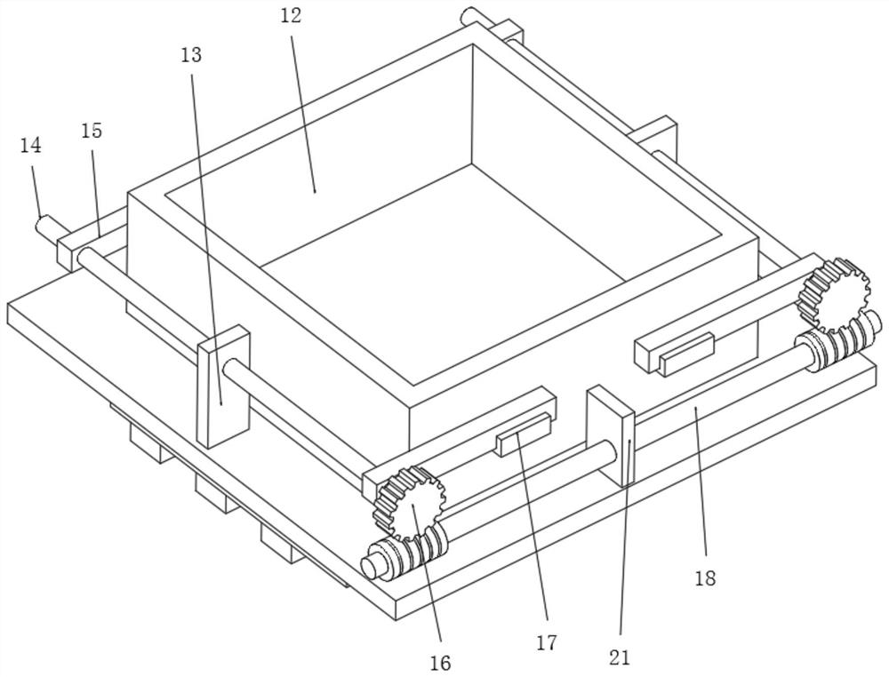
[0027] Embodiment 1: A self-floating rural ecological landscape plant planting device, comprising a floating plate 1, a casing 12 is placed in the middle of the upper end surface of the floating plate 1, and floating blocks 3 are placed on the left and right sides of the lower end surface of the floating plate 1. 1. The left and right sides of the lower end surface are fixedly connected with the fixed plate 2. The front ends of the left and right sides of the lower end surface of the floating plate 1 are slidably connected to the clamping plate 5 through the chute 4 and the slider 11. The middle of the lower end surface of the floating plate 1 is connected by a pin shaft. There are gears 7 and rotating plates 6 . The lower end of the rotating plate 6 is connected to the connecting rod 9 through the rotation of the pin shaft on both sides at the front and the rear. An L-shaped rod 8 is fixedly connected to the middle of the rear side of the lower end surface of the floating pla...

Embodiment 2

[0028] Embodiment 2: The difference between this embodiment and Embodiment 1 is that the middle parts of the front and rear sides of the upper end of the floating plate 1 are fixedly connected with the third support plate 21 , and the middle part of the third support plate 21 is rotatably connected with the worm 18 . A first support plate 13 is fixedly connected to the middle parts of the left and right sides of the upper end surface of the floating plate 1 , and a rotating rod 14 is rotatably connected to the upper end of the first support plate 13 . The front and rear ends of the rotating rod 14 are fixedly connected with plug-in blocks 15, the front end surface of the rotating rod 14 is fixedly connected with a worm wheel 16, the worm wheel 16 is engaged with a worm 18, and the left and right sides of the front and rear ends of the housing 12 are fixedly connected with groove blocks 17. , the groove block 17 is plugged with the plug block 15 . By placing the casing 12 on th...


PUM


Abstract

The invention discloses a self-floating rural ecological landscape plant planting device which comprises a floating plate, a shell is placed in the middle of the upper end face of the floating plate, floating blocks are placed on the left side and the right side of the lower end face of the floating plate, and fixing plates are fixedly connected to the left side and the right side of the lower end face of the floating plate. Clamping plates are slidably connected to the front ends of the left and right sides of the lower end face of the floating plate through sliding grooves and sliding blocks, and a gear and a rotating plate are rotatably connected to the middle of the lower end face of the floating plate through pin shafts. The invention relates to the technical field of greening engineering ecological landscapes. The self-floating village ecological landscape plant planting device solves the problems that according to an existing self-floating village ecological landscape plant planting device, the number and buoyancy of floating blocks are inconvenient to control, and a shell is inconvenient to disassemble easily.

Description

technical field [0001] The invention relates to the technical field of greening engineering ecological landscape, in particular to a self-floating rural ecological landscape plant planting device. Background technique [0002] Landscaping is a place to provide people with a good rest, cultural entertainment, close to nature, and meet people's desire to return to nature. It is an important measure to protect the ecological environment and improve the urban living environment. It is the application of engineering technology to express garden art, so that the engineering structures on the ground and the garden landscape are integrated. The water landscape is the main form of garden engineering. [0003] The existing self-floating rural ecological landscape plant planting is inconvenient to control the number and buoyancy of the buoys, and it is inconvenient to have a simple disassembly effect on the shell. SUMMARY OF THE INVENTION [0004] (1) Technical problems solved [...

Claims


Application Information

Patent Timeline
Patent Type & Authority Applications(China)
IPC IPC(8): A01G9/02
CPCA01G9/02Y02P60/21
Inventor 方小兵王松华张鹏李环瑞郭祺
Owner 江苏景古规划设计研究有限公司
Learn More