
Manufacturing method of high-rigidity drawing arm and drawing arm manufactured by using same

A manufacturing method and high-rigidity technology, which can be used in claw arms, manufacturing tools, manipulators, etc., can solve the problems of increased transmission power, high energy consumption costs, and heavy weight of pulling arms, achieving low cost and reducing energy consumption costs. , low cost effect

Active Publication Date: 2022-07-22
GUANGDONG TOPSTAR TECH
View PDF6 Cites 0 Cited by
  • Summary
  • Abstract
  • Description
  • Claims
  • Application Information

AI Technical Summary

Problems solved by technology

Such an extraction arm is too heavy, the transmission power needs to be increased, and the energy consumption cost increases

Method used


Image

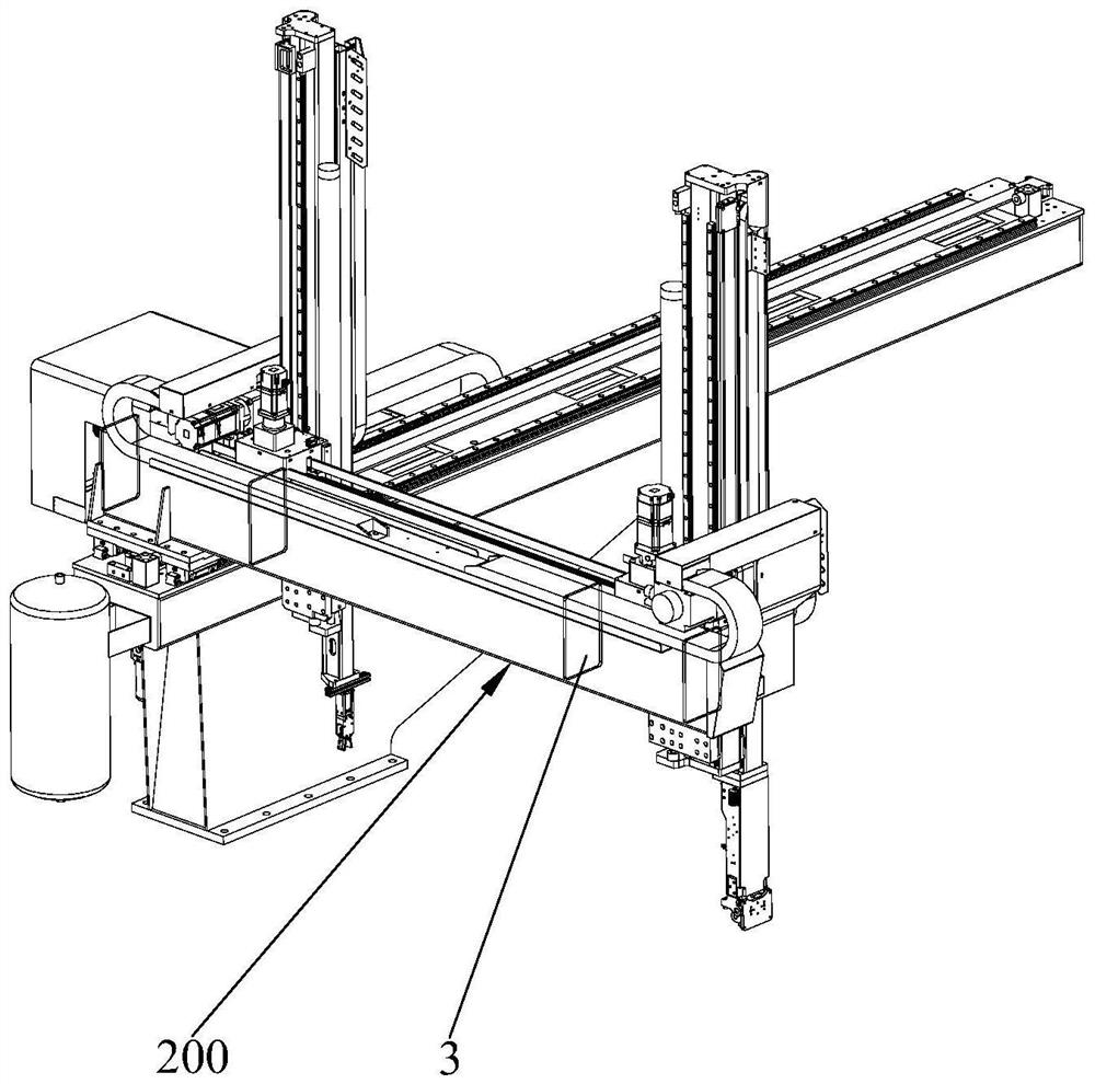
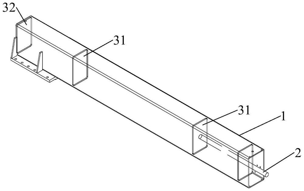
  • Manufacturing method of high-rigidity drawing arm and drawing arm manufactured by using same
  • Manufacturing method of high-rigidity drawing arm and drawing arm manufactured by using same
  • Manufacturing method of high-rigidity drawing arm and drawing arm manufactured by using same

Examples


Embodiment Construction

[0031] In order to describe the technical content and structural features of the present invention in detail, further description will be given below with reference to the embodiments and the accompanying drawings.

[0032] see Figure 2 to Figure 7 , the manufacturing method S100 of the high-rigidity pulling arm of the present invention comprises the following steps:

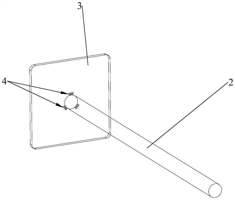
[0033] Step S01 : providing a steel bar 2 , a sealing plate 3 and a welding gun, and the welding gun welds the steel bar 2 on the surface of the sealing plate 3 by spot welding, so that the steel bar 2 is connected with the sealing plate 3 . Specifically, in this step, the number of welding points 4 between the steel rod 2 and the sealing plate 3 is 2-3, the welding points 4 are spaced apart around the circumference of the steel rod 2 , and the steel rod 2 is welded to the center of the sealing plate 3 Location. Spot welding is used for welding between the steel rod 2 and the sealing plate 3, so the subsequen...


PUM


Abstract

The invention discloses a manufacturing method of a high-rigidity drawing arm body, which comprises the following steps of: (1) providing a steel bar, a sealing plate and a welding gun, and welding the steel bar on the surface of the sealing plate by the welding gun in a spot welding manner; (2) providing a hollow drawing arm body with two open ends, enabling the sealing plate to face the opening of the drawing arm body, and enabling the steel bar and the sealing plate to extend into the drawing arm body; (3) a measuring tool is provided, one end of the measuring tool extends into the drawing arm body and abuts against the sealing plate, and a numerical value on the measuring tool is read; (4) a welding gun extends into the drawing arm body, and the sealing plate and the drawing arm body are welded through the welding gun in a segmented welding mode; and (5) beating and taking out the steel bar. And (6) the steps are repeated, and the multiple sealing plates are arranged in the drawing arm body at intervals. The high rigidity effect can be achieved under the condition that the weight and the thickness of the drawing arm are not increased. And meanwhile, the weight of the drawing arm is not excessively increased, so that the energy consumption cost can be reduced.

Description

technical field [0001] The invention relates to the field of manufacture of manipulator pulling arms, in particular to a method for manufacturing a high-rigidity pulling arm and a pulling arm produced by the method. Background technique [0002] The pull-out arm of the large manipulator is generally made of steel flat pass or square pass. In order to improve rigidity, two are usually welded together, or the cross-sectional size and thickness of the flat pass or square pass are increased. Such a pulling arm is too heavy, the transmission power needs to be increased, and the energy consumption cost is increased. [0003] On the market, however, there are few manipulator arms that can improve rigidity and reduce energy costs without increasing the thickness and cross-sectional size. [0004] Therefore, there is an urgent need for a method for manufacturing a high-rigidity pulling arm that can reduce energy costs while increasing the rigidity of the pulling arm, and a pulling a...

Claims


Application Information

Patent Timeline
Patent Type & Authority Applications(China)
IPC IPC(8): B25J18/00B25J19/00
CPCB25J18/00B25J19/00Y02E30/30
Inventor 廖伟传吴丰义吴丰礼
Owner GUANGDONG TOPSTAR TECH
Learn More