
13-segment carrier pulse width modulation method and system and related components

A pulse width modulation, three-stage technology, applied to electrical components, output power conversion devices, AC power input conversion to DC power output, etc., can solve the problem of uncontrollable and unreachable current harmonic performance of converters drop and other issues

Pending Publication Date: 2022-07-15
SHENZHEN INVT ELECTRIC
View PDF0 Cites 2 Cited by
  • Summary
  • Abstract
  • Description
  • Claims
  • Application Information

AI Technical Summary

Problems solved by technology

[0003] The control core of the three-level converter is to control the switching state of each power device. When each power device switches according to the set driving signal, the three-level converter can output the set voltage vector, and then accurately output the target. voltage, and when the power devices are not driven normally, the output voltage of the three-level converter will be distorted, and even the operation of the converter will be uncontrollable
However, in the area of ​​low modulation degree, the phase voltage pulse width of the existing carrier pulse width modulation method and space vector modulation method is relatively narrow, which cannot achieve the effect that the phase voltage pulse width is greater than the minimum switching time of the device, resulting in the output voltage amplitude Distortion and Current Harmonic Degradation

Method used


Image

  • 13-segment carrier pulse width modulation method and system and related components
  • 13-segment carrier pulse width modulation method and system and related components
  • 13-segment carrier pulse width modulation method and system and related components

Examples


Embodiment Construction

[0061] The technical solutions in the embodiments of the present invention will be clearly and completely described below with reference to the accompanying drawings in the embodiments of the present invention. Obviously, the described embodiments are only a part of the embodiments of the present invention, but not all of the embodiments. Based on the embodiments of the present invention, all other embodiments obtained by those of ordinary skill in the art without creative efforts shall fall within the protection scope of the present invention.

[0062] Taking the above two factors into consideration, in order to drive high-power devices correctly, the pulse-width modulation method of high-power three-level converters in the low-voltage regime region should be able to ensure the pulse width of the phase voltage. However, in the low regulation region, the phase voltage pulse width of the existing carrier pulse width modulation method and the space vector modulation method are bo...


PUM


Abstract

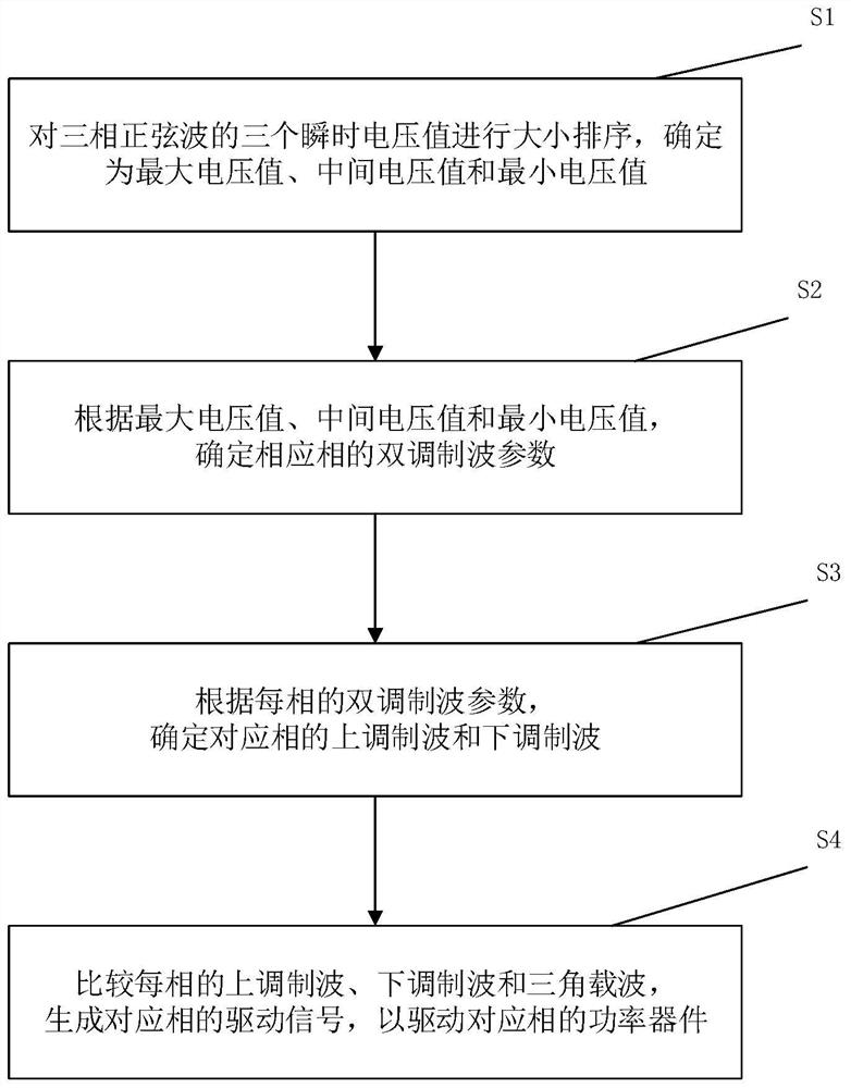
The invention discloses a thirteen-segment carrier pulse width modulation method and system and related components, relates to the field of carrier pulse width modulation, is applied to a three-level converter, and comprises the following steps: sorting three instantaneous voltage values of a three-phase sine wave; according to the maximum voltage value, the intermediate voltage value and the minimum voltage value, determining a dual-modulation wave parameter of the corresponding phase; determining an upper modulation wave and a lower modulation wave of the corresponding phase according to the dual modulation wave parameter of each phase; and comparing the upper modulation wave, the lower modulation wave and the triangular carrier wave of each phase to generate a driving signal of the corresponding phase. The driving signal output by the modulation method can ensure that the phase voltage pulse width of a low modulation degree region is greater than the minimum switching time of a device, so that narrow pulses are effectively eliminated, the target voltage is accurately output, and the effects of reducing current harmonic distortion and improving neutral-point voltage self-balance of the three-level converter are achieved. In addition, only amplitude calculation is needed, and the method has the advantages of being simple in calculation and easy to implement.

Description

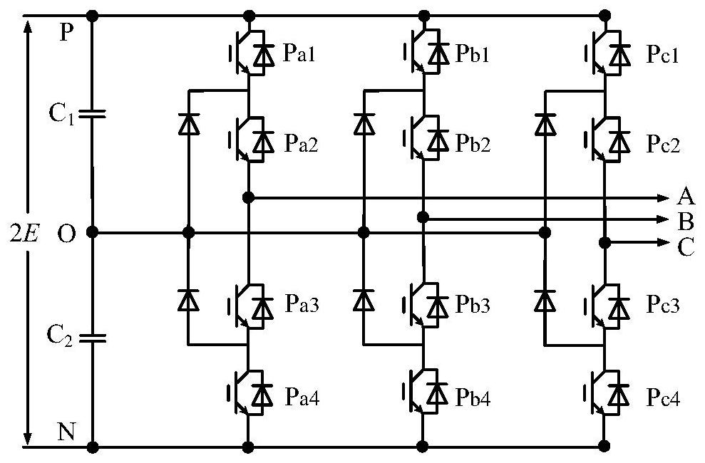
technical field [0001] The invention relates to the field of carrier pulse width modulation, in particular to a thirteen-segment carrier pulse width modulation method, system and related components. Background technique [0002] Due to the advantages of low voltage stress of power devices, good output power quality, and relatively simple structure and control, three-level neutral point clamped (NPC) converters, referred to as three-level converters, are used in grid reactive power. Compensation, rail transit, wind power generation, metallurgical mining and other fields have been widely used. figure 1 It is the main circuit topology of the three-level converter. [0003] The control core of the three-level converter is to control the switching state of each power device. When each power device switches according to the set driving signal, the three-level converter can output the set voltage vector, and then accurately output the target. When the power devices are not driven...

Claims


Application Information

Patent Timeline
IPC IPC(8): H02M7/487H02M7/5387
CPCH02M7/487H02M7/5387
Inventor 高瞻周志达耿程飞宋茂林吴轩钦
Owner SHENZHEN INVT ELECTRIC
Learn More