
Wiper arm

A wiper arm and wiper technology, applied in vehicle cleaning, vehicle maintenance, circuits, etc., can solve problems such as inability to ensure positioning and poor orientation

Inactive Publication Date: 2004-04-21
ROBERT BOSCH GMBH
View PDF3 Cites 0 Cited by
  • Summary
  • Abstract
  • Description
  • Claims
  • Application Information

AI Technical Summary

Problems solved by technology

Although the manufacturing tolerances of the large number of individual components in the windshield wiper and its transmission mechanism are very small, the accumulation of tolerances, the tolerances when fastening to the car body and the tolerances of the body itself are large enough to make it impossible to guarantee the quality in mass production. best position
The wiper device can achieve good orientation along the transverse direction of the vehicle due to its large length / width ratio, but poor orientation in other directions, especially the longitudinal direction of the vehicle

Method used


Image

  • Wiper arm
  • Wiper arm
  • Wiper arm

Examples


Embodiment Construction

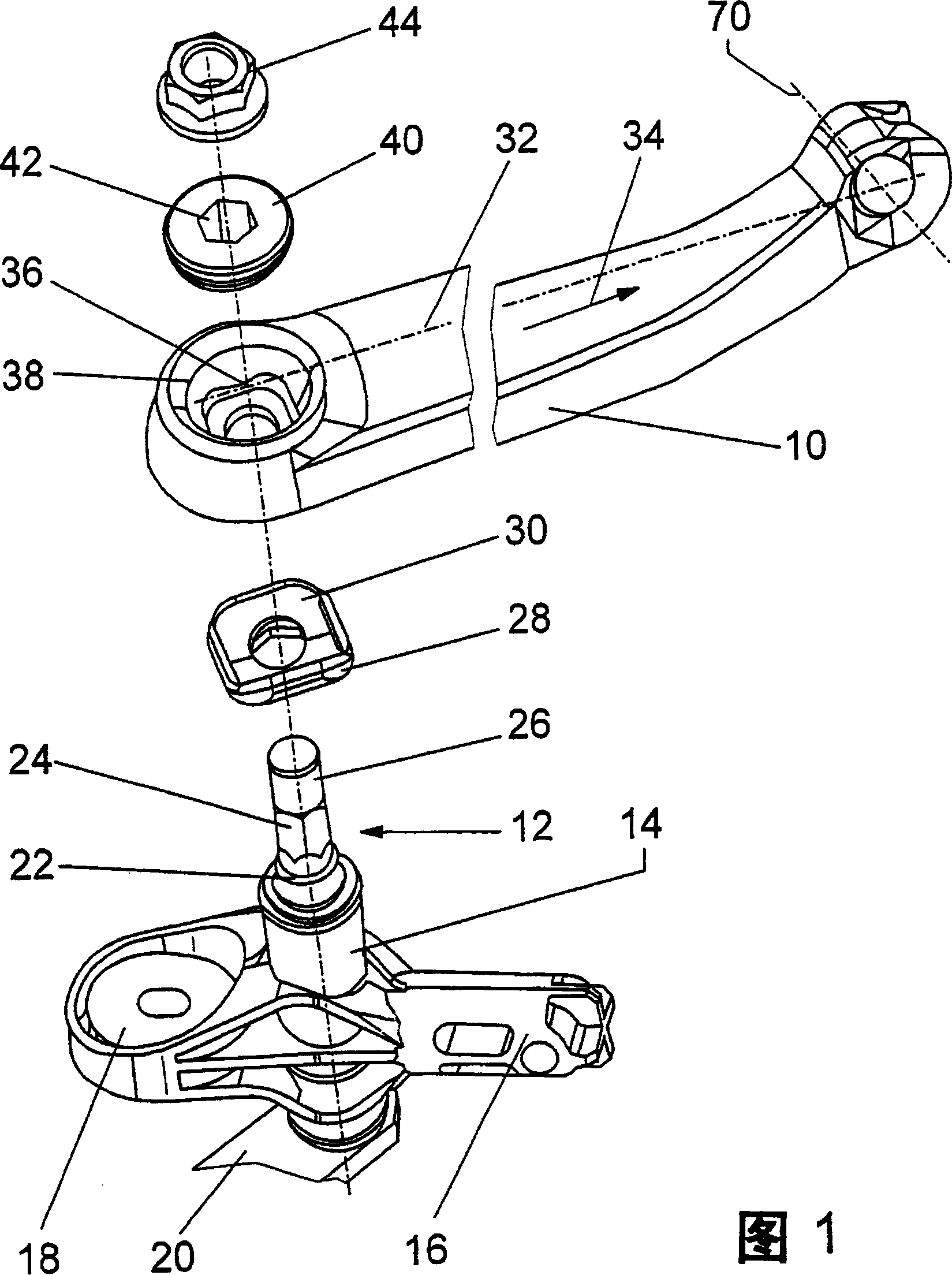
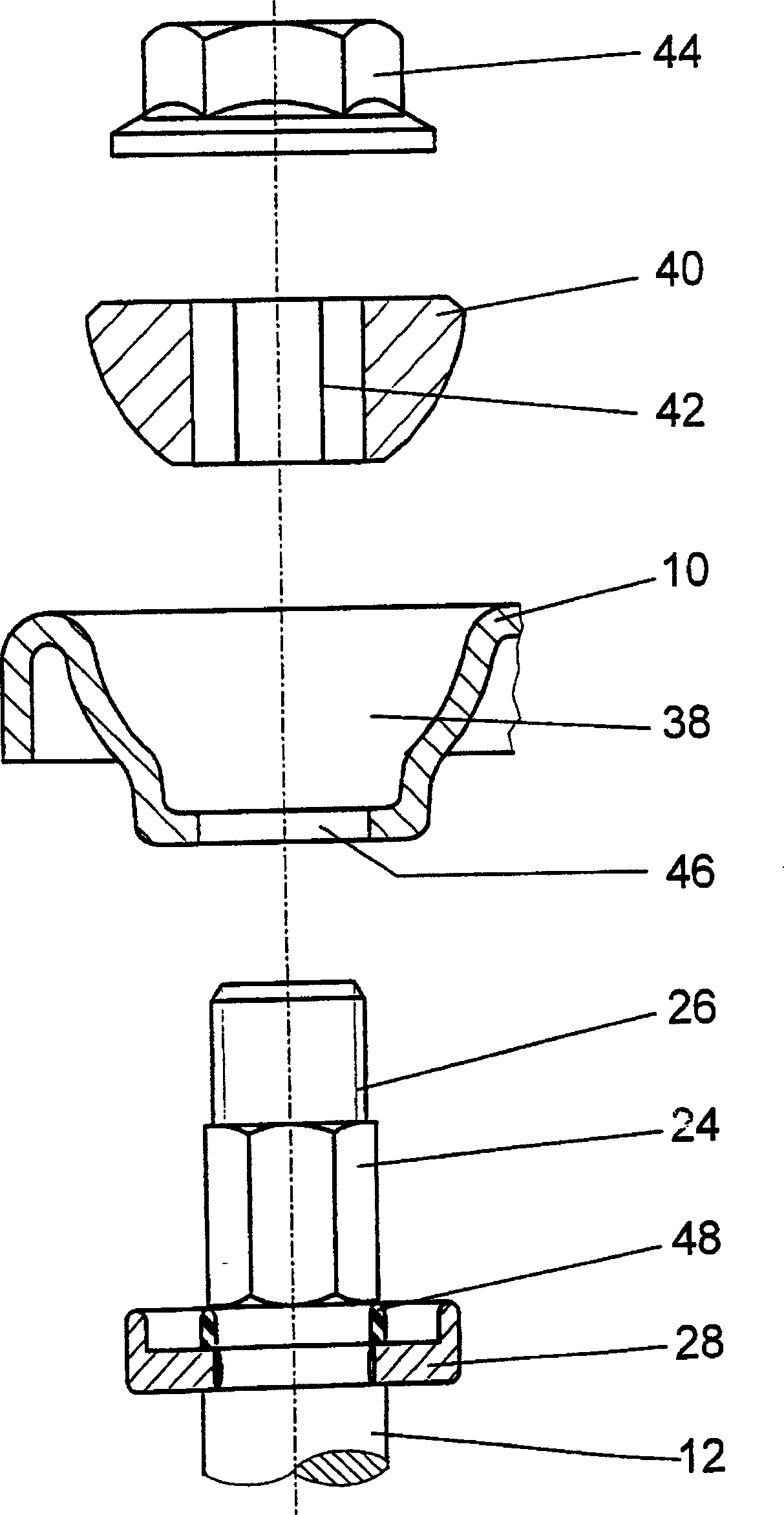
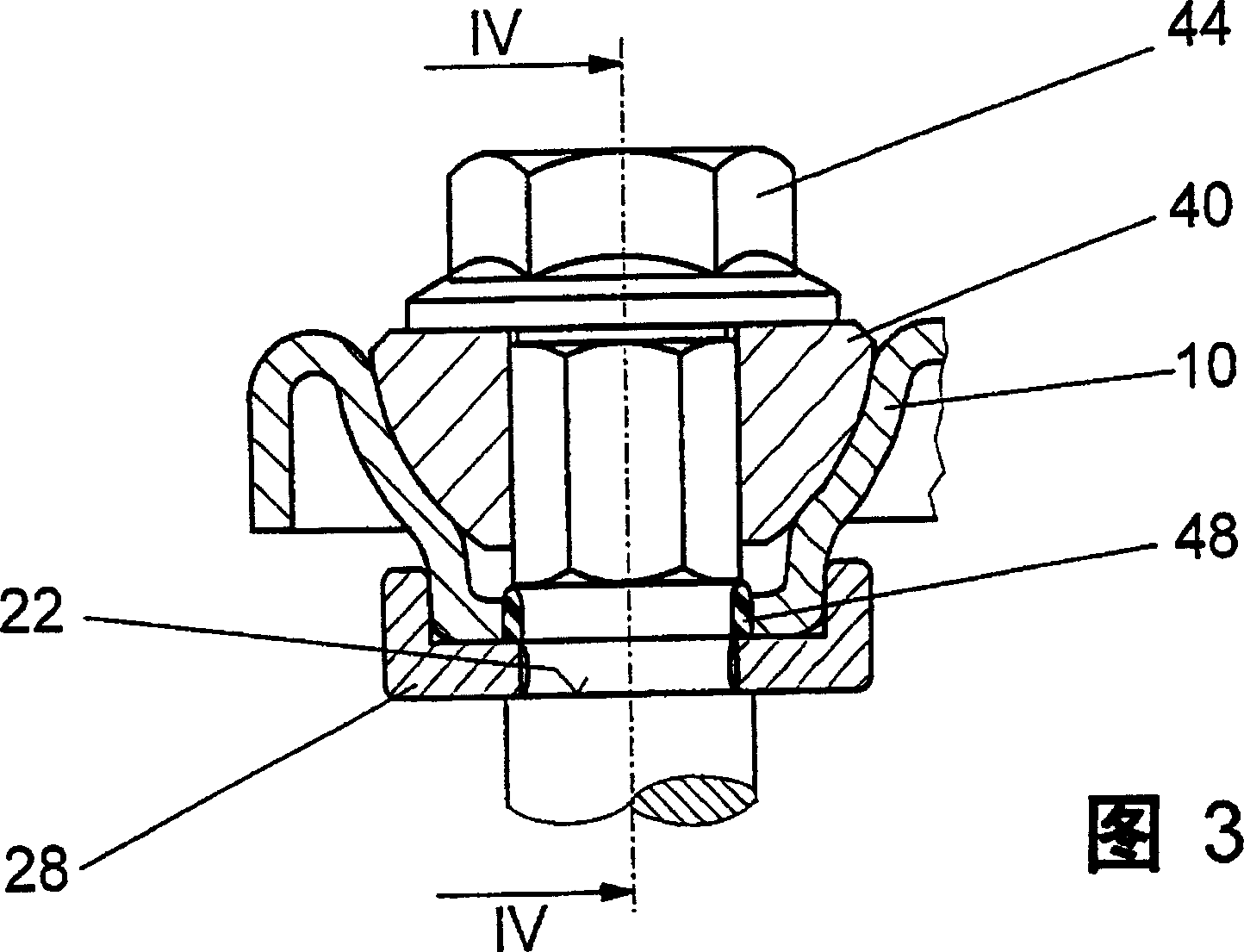
[0027]The figures show only a part of a wiper device with a wiper arm and are only necessary for understanding the invention. The components belonging to the wiper arm include a fastening component 10 which is fastened to a drive shaft 12 . The drive shaft 12 is mounted in a bearing housing 14 which has a connecting tube 16 and a fastening eye 18 for a wiper carrier, not shown here. Through the latter, the bearing housing 14 is fastened to a not-shown vehicle body. The drive shaft 12 is driven by a wiper motor via a lever drive and a crank 20 which is fixedly connected at one end to the drive shaft 12 . The free end of the drive shaft 12 has a shoulder 22 and a profile 24 with a polygonal cross-section and a thread 26 connected thereto. On the free end of the drive shaft 12 is inserted a washer 28 which is supported on the shoulder 22 but is able to rotate about the drive shaft 12 . A concave cylindrical bearing surface 30 is formed in the washer 28 toward the fastening com...


PUM


Abstract

The invention relates to a wiper arm with a hinged wiper blade and a fixing part (10) for fixing to a drive shaft (12). This is done by inserting said shaft through a widening recess (38) of the fixing part (10). A screw nut (44) fastens the fixing part (10) and the drive shaft (12) against a locating surface (30) by means of a clamping part (40, 50) that matches the recess (38). According to the invention, the contact surface (66) between the clamping part (40, 50) and the fixing part (10) form part of the surface of a sphere and the locating surface (30) forms part of a surface area of a cylinder, the axis of the cylinder (32) extending through the center point of the sphere (36) and parallel to the longitudinal direction (34) of the wiper blade.

Description

technical field [0001] The invention relates to a wiper arm. Background technique [0002] Existing windshield wipers have a wiper arm consisting of a fastening component and a hinge component with a wiper lever which is articulated thereon via a folded hinge. A hooked end of the wiper rod hooks into a hitch box for the wiper blade, which consists of two side walls (Seitenwangen) of a central bow (Buegel) and includes a hinge pin Connect components. The hinge formed in this way drives the wiper blade during the pivoting process of the wiper blade on the windshield of the motor vehicle. [0003] In general, wiper blades have a load-bearing bow system comprising several components with subordinate bows hinged to a central bow, at least some of which are aided by clips on their ends Clip a wiper blade to its top strip. The multi-component load-bearing bow system and the elastic rail inserted into the roof strip enable the wiper blade to adapt to the curved windshield with u...

Claims


Application Information

Patent Timeline
Patent Type & Authority Patents(China)
IPC IPC(8): B60S1/32B60S1/34
CPCB60S1/3436B60S1/3461B60S1/34Y10T403/32311Y10T403/32319Y10T403/32368Y10T403/32418B60S1/32
Inventor 约阿希姆·策默
Owner ROBERT BOSCH GMBH
Learn More