Cloth printing equipment

A printing equipment and fabric technology, applied in printing, printing presses, rotary printing presses, etc., to improve production efficiency and reduce workload

Inactive Publication Date: 2022-06-10
徐继念
View PDF0 Cites 0 Cited by
  • Summary
  • Abstract
  • Description
  • Claims
  • Application Information

AI Technical Summary

Problems solved by technology

Therefore, the inventor believes that the printing equipment has the disadvantage of increasing the workload of production personnel, which needs to be improved

Method used


Image

  • Cloth printing equipment
  • Cloth printing equipment
  • Cloth printing equipment

Examples


Embodiment Construction

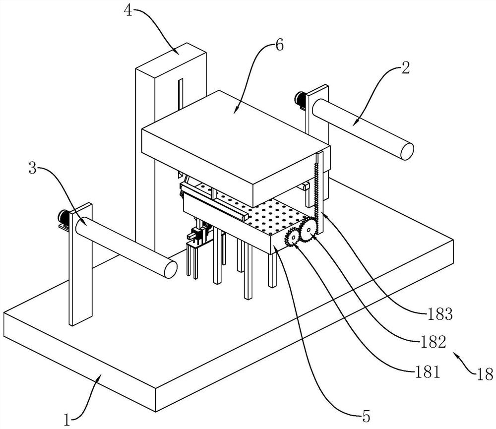
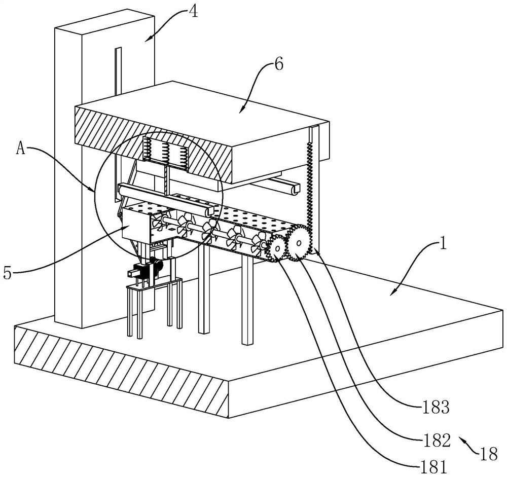
[0020] refer to image 3 and Figure 4 One end of the mounting shaft 15 extends to the outside of the receiving block 5, the control mechanism 18 includes a driven gear 181 fixed to the end of the mounting shaft 15 outside the receiving block 5, and the side wall of the receiving block 5 is rotatably connected with a transmission gear 182. The transmission gear 182 meshes with the driven gear 181 , so that the transmission gear 182 can drive the driven gear 181 to drive the installation shaft 15 to rotate. At the same time, the number of teeth of the driven gear 181 is less than that of the transmission gear 182, which reduces the transmission ratio, so that the installation shaft 15 can rotate more times.

[0021] refer to image 3 and Figure 4 , the lower end of the support block 6 is vertically fixedly connected with a driving rack 183 , and the driving rack 183 is meshed with the transmission gear 182 . When the supporting block 6 moves downward, the driving rack 183 ...


PUM


Abstract

The cloth printing equipment comprises a workbench, a feeding roller, a supporting frame and a receiving roller, a bearing block is fixed to the side wall of the supporting frame, a supporting block is vertically and slidably connected to the side wall of the supporting frame, a printing plate is fixed to the lower end of the supporting block, two mounting grooves are formed in the lower end of the supporting block, and a mounting rod is vertically and slidably arranged in each mounting groove in a penetrating mode; a driving mechanism used for driving the supporting block to vertically move is arranged between the supporting frame and the workbench, and a control mechanism used for driving the corresponding mounting rod to vertically move is arranged in each mounting groove. The control mechanism comprises limiting plates fixed to the upper ends of the mounting rods, control springs arranged in the mounting grooves and limiting rings fixed to ports of the mounting grooves, the limiting rings are used for blocking the corresponding limiting plates, and the control springs can drive the corresponding mounting rods to move downwards. The control mechanism is used for driving the corresponding mounting rods to abut against the cloth, so that the cloth can be in a tightened state, and automatic flattening of the cloth is achieved.

Description

technical field [0001] The invention relates to the field of printing equipment, in particular to a cloth printing equipment. Background technique [0002] Printing equipment is a device that prints colors or patterns on the surface of objects. When fabrics are produced, it is usually necessary to use printing equipment to print advertisements or other promotional slogans on the surface of fabrics. [0003] The printing equipment in the related art usually includes a workbench and a printing plate vertically slidably arranged on the workbench. When the cloth needs to be printed, the cloth is fed through the feeding roller, and then the pattern is printed on the cloth through the printing plate. surface. Subsequently, the cloth is rewound by the take-up roller, thereby realizing the printing operation on the cloth. The above-mentioned fabrics should include flexible materials such as woven bags and linen, and only flexible materials need to be smoothed before printing. [...

Claims


Application Information

Patent Timeline
Patent Type & Authority Applications(China)
IPC IPC(8): B41F17/00B41F13/02B41F23/04
CPCB41F17/003B41F13/02B41F23/0426B41P2217/10
Inventor 徐继念
Owner 徐继念
Why Eureka
Try Eureka