
Rotatable connecting structure

A technology of rotating connection and connecting ears, which is applied in the direction of flexible/rotatable wire connectors, connections, parts of connection devices, etc., which can solve problems such as increasing the overall cost of equipment, cable blockage, and the influence of hinge rotatable angles

Pending Publication Date: 2022-06-07
CHINA MOBILE CHENGDU INFORMATION & TELECOMM TECH CO LTD +1
View PDF5 Cites 0 Cited by
  • Summary
  • Abstract
  • Description
  • Claims
  • Application Information

AI Technical Summary

Problems solved by technology

[0006] 1. After the cable is wound on the hinge, it is usually necessary to reserve a certain length of excess cable. After the hinge rotates, the cable will continue to wind on the shaft at a certain angle. If there is no excess cable reserved, it will not be able to continue winding
[0007] 2. As mentioned in 1, on the contrary, if the hinge is reversely rotated with the cable wound on the shaft, more cables will be blocked in the space inside the hinge; therefore, the existing way of connecting cables inside the hinge, the hinge The rotatable angle is affected by the twisted cable
[0008] 3. In most cases, equipment manufacturers set a mechanical limit on the hinge to limit the rotation angle of the hinge. For example, the maximum opening and closing angle between the screen part and the keyboard part of most laptops is 100°. If the angle exceeds the limit, it will Damage to the equipment, so equipment manufacturers need to customize hinges with mechanical limit structures, different opening and closing angles need to customize different hinges, the cost of customization is high, and the overall cost of the equipment is increased

Method used


Image

  • Rotatable connecting structure
  • Rotatable connecting structure
  • Rotatable connecting structure

Examples


Embodiment Construction

[0032] The features and exemplary embodiments of various aspects of the present application will be described in detail below. In order to make the purpose, technical solutions and advantages of the present application more clear, the present application will be further described in detail below with reference to the accompanying drawings and specific embodiments. It should be understood that the specific embodiments described herein are only intended to explain the present application, but not to limit the present application. It will be apparent to those skilled in the art that the present application may be practiced without some of these specific details. The following description of the embodiments is merely to provide a better understanding of the present application by illustrating examples of the present application.

[0033] It should be noted that, in this document, relational terms such as first and second are only used to distinguish one entity or operation from an...


PUM


Abstract

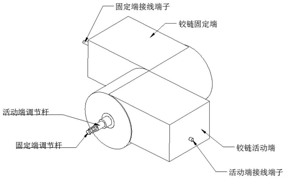
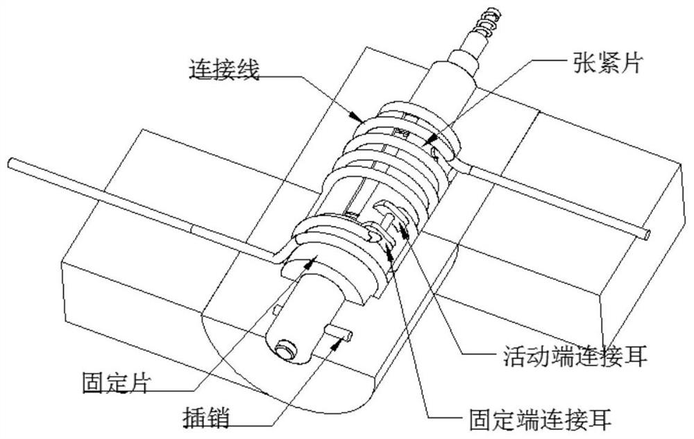
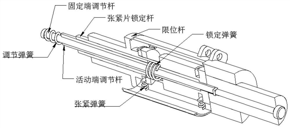
The invention provides a rotatable connecting structure. The rotatable connecting structure comprises a hinge fixed end and a hinge movable end, a fixed end wiring terminal for wiring is arranged at the end part of the hinge fixed end; a movable end wiring terminal for wiring is arranged at the end part of the hinge movable end; the hinge fixed end and the hinge movable end are movably connected through a rotating shaft, and a fixed end adjusting rod and a movable end adjusting rod are arranged in the rotating shaft so as to adjust the opening and closing angle of the hinge. According to the embodiment of the invention, the opening and closing angle of the hinge can be adaptively adjusted.

Description

technical field [0001] The present application belongs to the technical field of electronic equipment connection structure design, and in particular relates to a rotatable connection structure. Background technique [0002] A hinge, also known as a hinge, is a mechanical device used to connect two solids and allow relative rotation between them. The hinge may be constructed of movable components, or of collapsible material. [0003] The hinge structure is widely used in various fields. For example, the notebook computer uses the hinge structure to connect the display part and the keyboard part, so that the notebook computer can be opened, closed and folded. [0004] In the field of electronic equipment, it is usually necessary to set cables at both ends of the hinge. For example, a notebook computer needs to pass the connecting cable of the display through the hinge, so that the display can communicate with the main board provided in the keyboard part through the connecting...

Claims


Application Information

Patent Timeline
Patent Type & Authority Applications(China)
IPC IPC(8): H01R35/00H01R13/502
CPCH01R35/00H01R13/502
Inventor 王杨李廷龙黄铁脉刘朋
Owner CHINA MOBILE CHENGDU INFORMATION & TELECOMM TECH CO LTD
Learn More