Vibration isolation coupling design and forming process
A molding process and coupling technology, used in couplings, elastic couplings, mechanical equipment, etc., can solve the problems of raising the vibration level of the whole machine, and achieve the effect of reducing the vibration level and eliminating vibration coupling.
Pending Publication Date: 2022-06-07
AEROSPACE SHENZHOU AIRCRAFT
View PDF9 Cites 0 Cited by
- Summary
- Abstract
- Description
- Claims
- Application Information
AI Technical Summary
Problems solved by technology
In this type of unmanned helicopter, the vibration generated by the engine and the vibration generated by the rotor are coupled on the transmission system, which is likely to cause an increase in the vibration level of the whole machine. The vibration coupling between each other cannot be avoided, and the influence on the transmission system still exists
Method used
View moreImage
Smart ImageViewing Examples
Examples
Embodiment approach
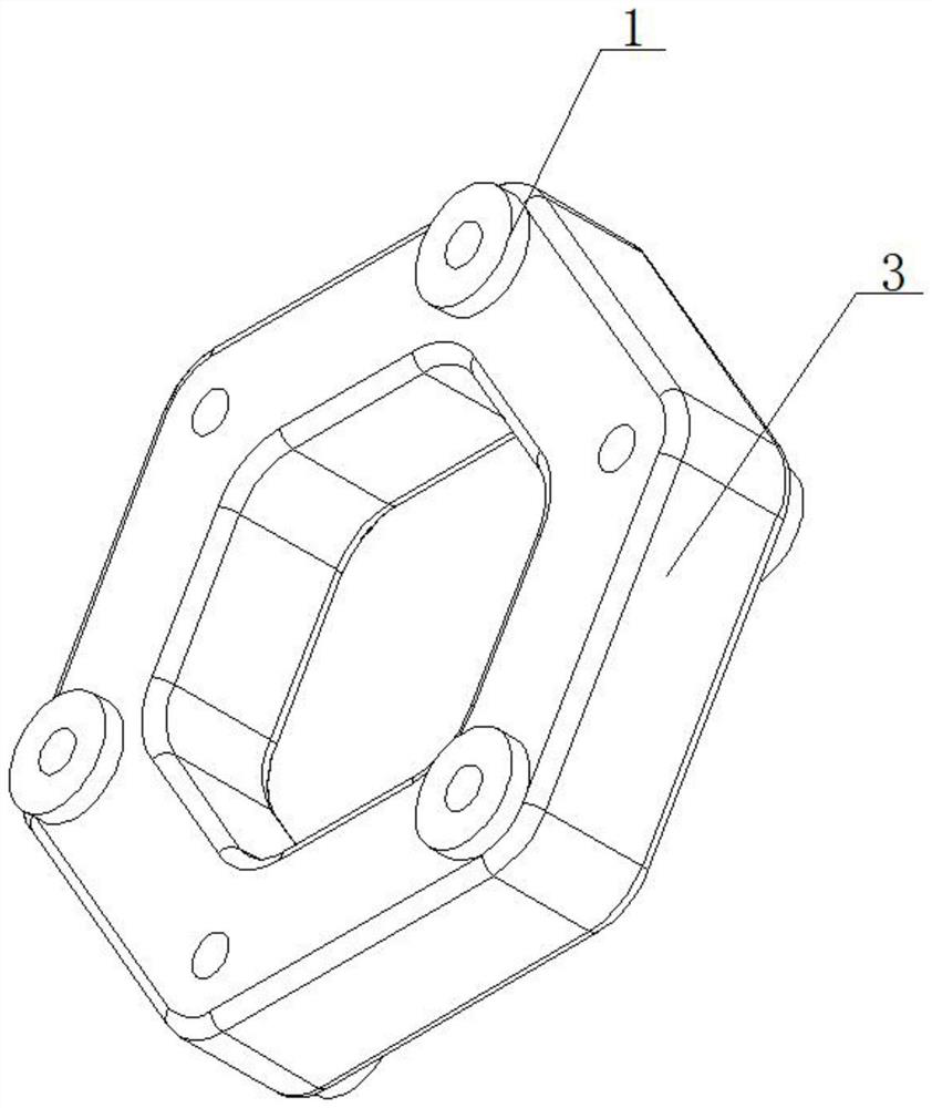
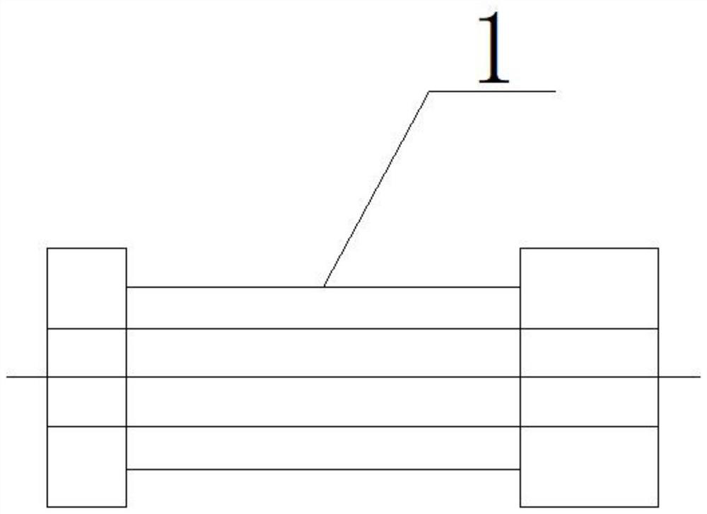
[0031] As a preferred embodiment of the present invention, metal pins are installed inside the metal pin sleeve 1 , and vulcanized rubber fillers are installed inside the vulcanized rubber 3 .
Login to View More PUM
 Abstract
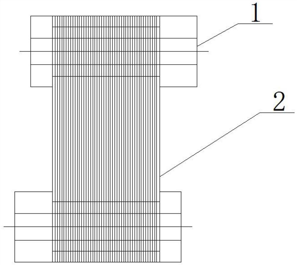
The invention provides a vibration isolation coupling design and forming process which comprises a vibration isolation coupling device body and is characterized in that the vibration isolation coupling device body comprises vulcanized rubber, a metal pin sleeve is mounted on the vulcanized rubber, a metal pin is mounted in the metal pin sleeve, and the metal pin is mounted in the metal pin sleeve. The metal pin sleeves are connected with each other through a Kailaff fiber bundle, a vulcanized rubber filler is mounted in the vulcanized rubber, a coupling end piece is mounted on the vulcanized rubber, and the coupling end piece is matched with the vulcanized rubber through a connecting bolt. While torque transmission is met, the vibration isolation capacity is achieved, vibration coupling is eliminated, and the vibration level of the whole machine is reduced.
Description
technical field [0001] The invention relates to the field of unmanned helicopter equipment, in particular to a design and molding process of a vibration isolation coupling. Background technique [0002] In recent years, the development speed of unmanned helicopters has been extremely rapid, and they have been widely used in many industries. At the same time that unmanned helicopters are used in various industries, the vibration coupling phenomenon of unmanned helicopters has seriously affected the structure of unmanned helicopters. life, especially for unmanned helicopters with piston engines. In this type of unmanned helicopter, the vibration generated by the engine and the vibration generated by the rotor are coupled on the transmission system, which can easily lead to an increase in the vibration level of the whole machine. Although the reduction of the rotor system and the engine alone can play some role, The vibration coupling between them cannot be avoided, and the in...
Claims
Login to View More Application Information
Patent Timeline
 Patent Type & Authority Applications(China)
IPC IPC(8): B29C45/14F16D3/12
CPCB29C45/14F16D3/12B29C2045/1486
Inventor 刘涛姜明泽高晨李广磊
Owner AEROSPACE SHENZHOU AIRCRAFT
- R&D Engineer
- R&D Manager
- IP Professional
- Industry Leading Data Capabilities
- Powerful AI technology
- Patent DNA Extraction
Learn More Browse by: Latest US Patents, China's latest patents, Technical Efficacy Thesaurus, Application Domain, Technology Topic, Popular Technical Reports.
© 2024 PatSnap. All rights reserved.Legal|Privacy policy|Modern Slavery Act Transparency Statement|Sitemap|About US| Contact US: help@patsnap.com


