


Quick Research
Generate reliable direction feasibility study reports for your R&D in just a few steps.

Technical Q&A
Discover and master advanced knowledge NOW. Basics, ideas, possibilities, all at once.

Find Solutions
As an expert in R&D theories, this can generate solutions to your technical problems instantly.

Evaluate Feasibility
Analyze your overall solution with one click, know your potential R&D risks in advance.

Monitor Landscape
Get weekly tech updates, stay abreast of the latest tech innovations and key insights.
Crank rocker type limb training device
A limb training, crank rocker technology, which is applied to training equipment for adjusting coordination, training equipment for adjusting cardiovascular system, gymnastics equipment, etc. There are no problems such as ankle pump movement, which can achieve good ankle joint training effect, inhibit abnormal joint response, and eliminate the effect of local degrees of freedom.
- Summary
- Abstract
- Description
- Claims
- Application Information
AI Technical Summary
Problems solved by technology
Method used
Image


Examples
Embodiment 1
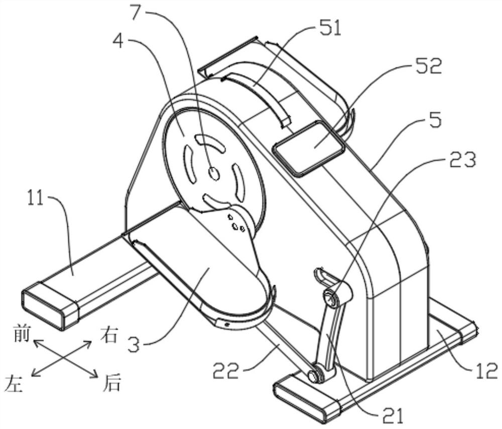
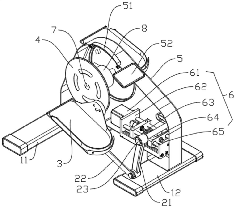
[0043] see Figure 1-4As shown, this embodiment introduces a crank-rocker-type limb training device, the crank-rocker-type limb training device includes a base and a crank 4, a rotating shaft 23, a rocker 21, a connecting rod arranged on the base 22. The supporting aid 3 and the first screw adjusting mechanism 6 . The crank 4 is rotatably installed on the base; the rotating shaft 23 is installed on the base and is located on one side of the crank 4, and the rotating shaft 23 can move relative to the base, so that the The rotating shaft 23 can move back and forth relative to the base; one end of the rocker 21 forms a rotating pair with the rotating shaft 23, and the rocker 21 can swing relative to the rotating shaft 23; one end of the connecting rod 22 is connected to the rotating shaft 23. The other end of the rocker 21 forms a rotating pair; the supporting aid 3 is fixedly installed on the connecting rod 22 , and the supporting aid 3 or the other end of the connecting rod 22...
Embodiment 2
[0061] see Figure 5 , this embodiment introduces another crank-rocker type limb training device. The difference between this embodiment and the first embodiment is the installation position of the support aid 3 on the connecting rod 22 through the second lead screw adjustment mechanism 9 .
[0062] Specifically, see Figure 5 , a second screw adjustment mechanism 9 is provided between the support aid 3 and the connecting rod 22 , and the second screw adjustment structure 9 is configured to adjust the support aid 3 on the connecting rod 22 To adjust the attitude inclination angle of the support aid 3 from the installation position on the top, the first lead screw adjustment mechanism 6 can be used as two realization structures for adjusting the attitude angle of the support aid 3 .
[0063] see Figure 5 , in this embodiment, the second screw adjustment mechanism 9 is arranged at the bottom of the support aid 3, and the second screw adjustment mechanism 9 includes a second s...
Embodiment 3
[0068] see Image 6 , this embodiment introduces a third crank-rocker type limb training device. The difference between this embodiment and the first embodiment is that the first screw driving device of the first screw adjusting mechanism 6 in this embodiment is a rotating handle 61 '. Other structures are basically the same, so the description is not repeated.
[0069] Specifically, see Image 6 , the rotating handle 61 ′ is arranged at the rear end of the outer side of the base, and the rotating handle 61 ′ is connected to the rear end of the first lead screw 63 in a driving connection, and the rotating handle 61 ′ can drive the first lead screw 63 . When the lead screw 63 rotates, the first lead screw nut 64 converts the rotation of the first lead screw 63 into the linear movement of the first lead screw nut 64 along the first lead screw 63, thereby driving all the The rotating shaft 23 moves along the length direction parallel to the first lead screw 63 to realize the a...
PUM
 Abstract
Description
Claims
Application Information
 - R&D Engineer
- R&D Manager
- IP Professional
- Industry Leading Data Capabilities
- Powerful AI technology
- Patent DNA Extraction
Browse by: Latest US Patents, China's latest patents, Technical Efficacy Thesaurus, Application Domain, Technology Topic, Popular Technical Reports.
© 2024 PatSnap. All rights reserved.Legal|Privacy policy|Modern Slavery Act Transparency Statement|Sitemap|About US| Contact US: help@patsnap.com