
Electronic device

A technology of electronic equipment and area, applied in the direction of TV, electrical components, color TV, etc., can solve problems such as affecting the appearance of electronic equipment

Active Publication Date: 2022-05-31
LENOVO (BEIJING) LTD
View PDF10 Cites 0 Cited by
  • Summary
  • Abstract
  • Description
  • Claims
  • Application Information

AI Technical Summary

Problems solved by technology

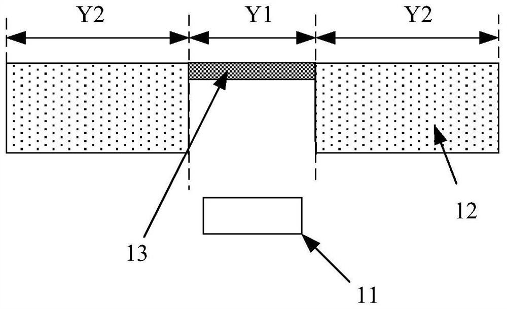
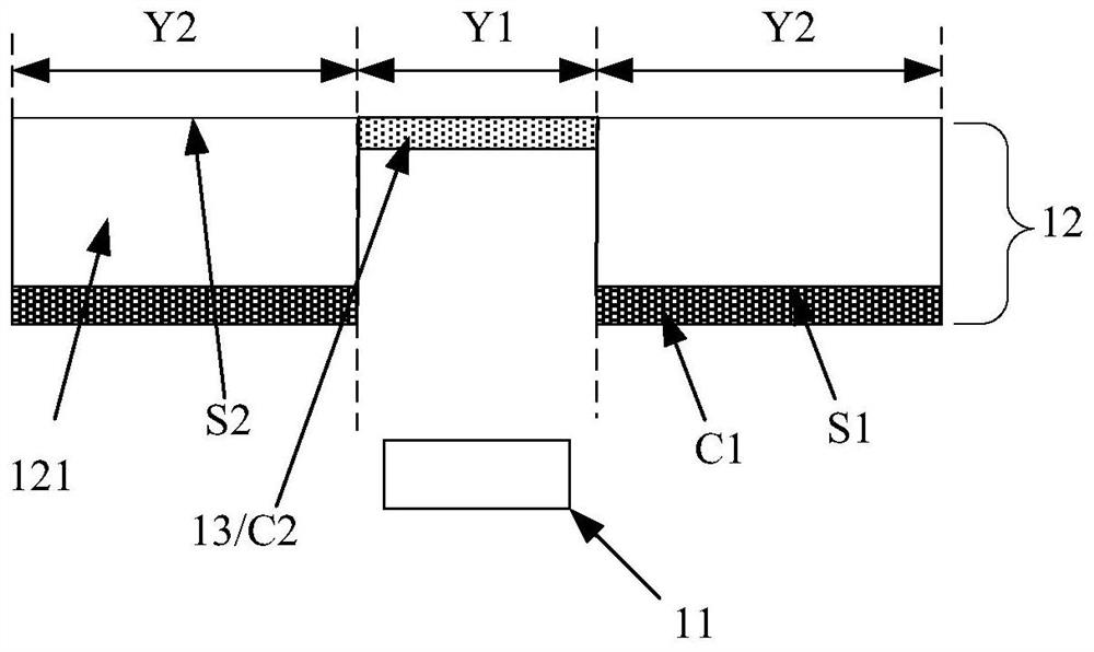
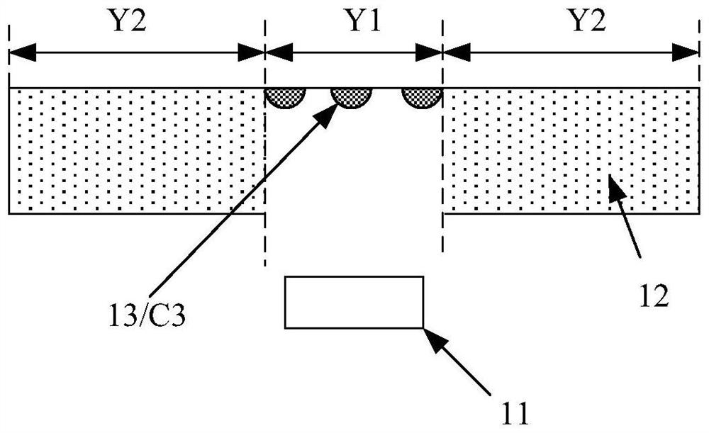
[0004] In electronic equipment, due to the integration of optical sensors, there will be visual differences between the window area used for light passing and other areas outside the window area, which will affect the appearance of electronic equipment

Method used


Image

  • Electronic device
  • Electronic device
  • Electronic device

Examples


Embodiment Construction

[0048] The following will clearly and completely describe the embodiments of the present application with reference to the drawings in the embodiments of the present application. Obviously, the described embodiments are only some of the embodiments of the present application, not all of them. Based on the embodiments in this application, all other embodiments obtained by persons of ordinary skill in the art without making creative efforts belong to the scope of protection of this application.

[0049] Taking an electronic device with a display component as an example, the display component includes but is not limited to an LCD display or an OLED display. The mainstream design solution is to realize the imaging function through an optical sensor under the screen.

[0050] The layout of the optical sensor under the screen mainly includes:

[0051] In the first way, the optical sensor is arranged under the display screen, that is, the optical sensor is arranged on the side away f...


PUM


Abstract

The invention discloses electronic equipment which comprises a body assembly which is located on the light incident side of an optical sensor and is provided with a first area and a second area at least adjacent to a part of the first area; the optical sensor is at least partially located in a light irradiation range passing through the first area and is used for imaging based on light; and the adjusting assembly is used for reducing the relative visual difference of the electronic equipment in the first area and the second area.

Description

technical field [0001] The present application relates to the technical field of electronic devices, and more specifically, relates to an electronic device with an imaging function. Background technique [0002] With the continuous advancement of science and technology, more and more electronic devices are widely used in people's daily life and work, bringing great convenience to people's daily life and work, and becoming an indispensable and important tool for people today. tool. [0003] In order to meet people's demands for imaging functions of electronic devices, many electronic devices are integrated with imaging functions. Electronic devices generally implement imaging functions by integrating optical sensors. When an optical sensor is integrated in an electronic device, it is necessary to form a window for light to pass through in the electronic device, so that the light enters the optical sensor for imaging. [0004] In electronic devices, due to the integration of...

Claims


Application Information

Patent Timeline
Patent Type & Authority Applications(China)
IPC IPC(8): H04N5/225G09F9/33G09F9/35
CPCG09F9/33G09F9/35H04N23/54H04N23/57H04N23/55G03B11/00H04N23/76H04N23/75
Inventor 苏跃峰樊小军
Owner LENOVO (BEIJING) LTD
Learn More