
Verification method of sectional type magnetic floater liquid level meter

A calibration method and magnetic float technology, applied in testing/calibration devices, liquid/fluid solids measurement, instruments, etc., can solve problems such as hidden safety hazards, high calibration cost, and cumbersome calibration process, so as to reduce calibration costs. , Improve the efficiency of verification and simplify the effect of verification steps

Pending Publication Date: 2022-05-13
SHANDONG NUCLEAR POWER CO LTD
View PDF0 Cites 0 Cited by
  • Summary
  • Abstract
  • Description
  • Claims
  • Application Information

AI Technical Summary

Problems solved by technology

[0004] 1) The filling and draining operation of the buoy is complicated, and the calibration efficiency is low; and the buoy includes a bottom water inlet and a top water outlet, which are difficult to block to maintain the water level, and liquid leakage or even running out is prone to occur during the calibration, which will bring Security risks
[0005] 2) The wet calibration method needs to connect a bypass liquid level plate to each buoy to determine the water level in the buoy, so the calibration cost is high, and the preparatory steps before the calibration involve multiple pipe joints and multiple The installation of the bypass liquid level plate, the calibration process is cumbersome
And this method is not very operable in actual application scenarios (narrow space, total height of more than ten meters), and cannot be verified based on actual installation scenarios
[0006] Therefore, the existing calibration methods have the problems of high calibration cost, complicated operation and low efficiency.

Method used


Image

  • Verification method of sectional type magnetic floater liquid level meter
  • Verification method of sectional type magnetic floater liquid level meter
  • Verification method of sectional type magnetic floater liquid level meter

Examples


Embodiment Construction

[0041] In order to enable those skilled in the art to better understand the solutions of the present invention, the following will clearly and completely describe the technical solutions in the embodiments of the present invention in conjunction with the drawings in the embodiments of the present invention. Obviously, the described embodiments are only It is an embodiment of a part of the present invention, but not all embodiments. Based on the embodiments of the present invention, all other embodiments obtained by persons of ordinary skill in the art without making creative efforts shall fall within the protection scope of the present invention.

[0042] It should be noted that the terms "first" and "second" in the description and claims of the present invention and the above drawings are used to distinguish similar objects, but not necessarily used to describe a specific sequence or sequence. It is to be understood that the data so used are interchangeable under appropriate ...


PUM


Abstract

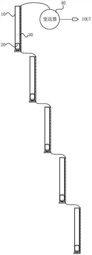
The invention discloses a verification method of a sectional type magnetic floater liquid level meter. The verification method of the sectional type magnetic floater liquid level meter comprises the steps that a pull-up assembly is provided; the pull-up assemblies are in one-to-one correspondence with the buoys; the lifting assembly comprises a lifting handle and a lifting rope, and the first end of the lifting rope is fixed to the lifting handle; the lifting rope extends into the buoy from a water outlet in the top of the corresponding buoy, and the second end of the lifting rope is fixed to the magnetic floater; the magnetic floats in the float bowl are sequentially pulled up to the top of the float bowl from the bottom of the float bowl by means of a pulling-up assembly, and the positions of the magnetic floats are kept; recording a first output signal of the transmitter obtained when the at least one magnetic floater is located at a first preset position in the pulling-up process; the first output signal is compared with the first standard electric signal, and whether the sectional type magnetic floater liquid level meter is normal or not is checked. According to the embodiment of the invention, simple and efficient verification of the sectional type magnetic floater liquid level meter can be realized, and the verification cost is reduced.

Description

technical field [0001] The invention relates to the technical field of instruments and meters, in particular to a calibration method for a segmented magnetic float liquid level gauge. Background technique [0002] The magnetic float level gauge can be used as a measuring instrument for the submerged liquid level in the containment of nuclear power plants. It is used to measure the submerged water level in the containment in nuclear power plant accident conditions, and provides post-accident monitoring functions for operators. Since the ability of the single-stage liquid level gauge to monitor liquid level changes is limited by the height of the buoy, and the height of the buoy is limited by the manufacturing process, the prior art introduces a segmented magnetic float level gauge. In order to ensure the measurement effect of the segmented magnetic float level gauge, it is necessary to calibrate it. [0003] The existing verification method is to fill the buoy of the liquid ...

Claims


Application Information

Patent Timeline
Patent Type & Authority Applications(China)
IPC IPC(8): G01F25/20
Inventor 赵瑜龙高奇峰刘辰星黄徳祎刘哲明姜昕妤李建伟王翔宇
Owner SHANDONG NUCLEAR POWER CO LTD
Learn More