Adhesive plate self-leveling storage stirring device
A mixing device and self-leveling technology, which is applied in the direction of cement mixing device, clay preparation device, mixing operation control device, etc., can solve the problems that affect the construction time, poor fixation of the mixing device, loose connection of the mixing tank, etc., to increase Work efficiency, increase the efficiency of stirring, improve the effect of stirring efficiency
- Summary
- Abstract
- Description
- Claims
- Application Information
AI Technical Summary
Problems solved by technology
Method used
Image
Examples
Embodiment 1
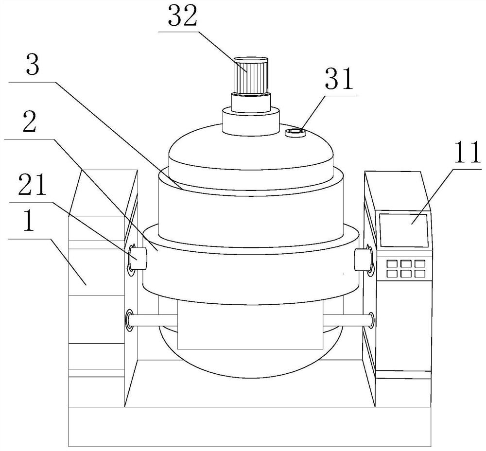
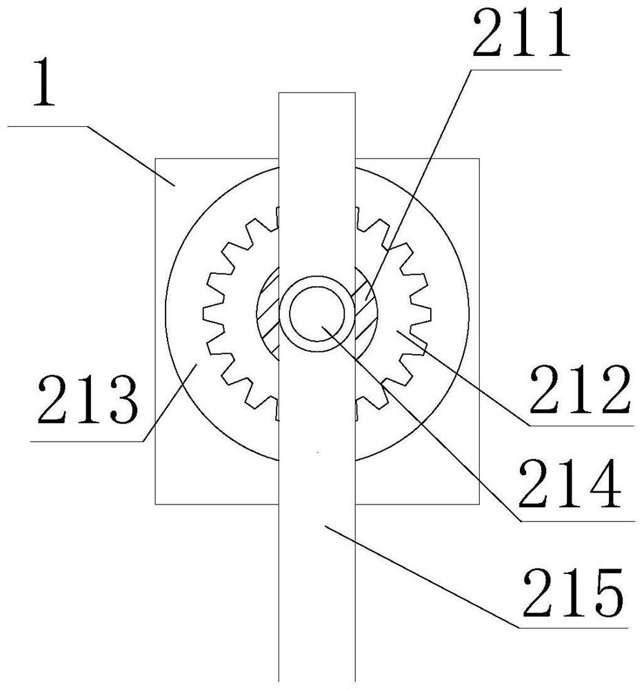
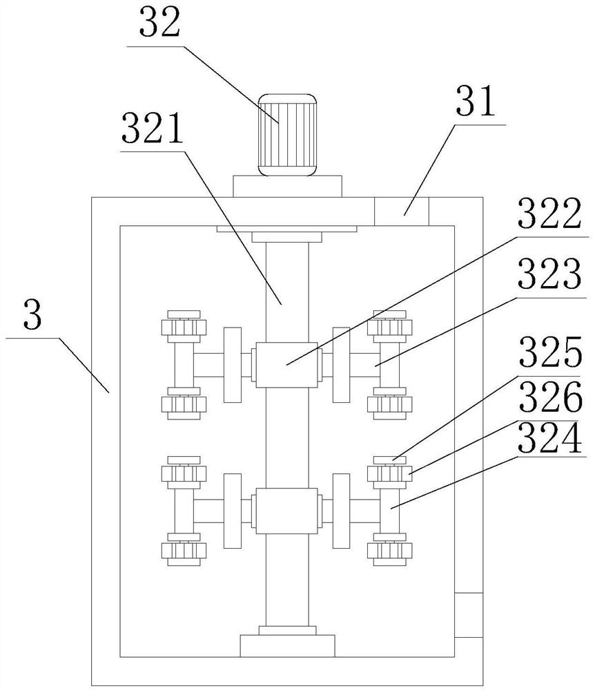
[0031] Such as Figure 1-6 As shown, the present invention provides a sticky plate self-leveling material storage and stirring device, including a stirring frame 1, a fixed sleeve frame 2 and a stirring tank 3, a control panel 11 is fixedly installed on the front of the stirring frame 1 right side, and the stirring frame 1 The inner side of the support rod 21 is movable installed with a support rod 21, and the other end of the support rod 21 is provided with a fixed socket frame 2, and the inside of the fixed socket frame 2 is fixedly installed with a stirring tank 3, and the top of the stirring tank 3 is provided with a material injection port 31. The side of feed opening 31 is fixedly installed with power motor 32, and the bottom of power motor 32 is fixedly installed with stirring column 321, and the outside of stirring column 321 is fixedly installed with rotating block 322, and the both sides of rotating block 322 are fixedly installed with stirring blade 323, fixed A rot...
Embodiment 2
[0034] Such as Figure 1-6 As shown, on the basis of Embodiment 1, the present invention provides a technical solution: preferably, a moisture-proof plate 3261 is fixedly installed on the outside of the rotating block 325, and a heating mechanism 3262 is fixedly installed on the inside of the moisture-proof plate 3261, and the heating mechanism 3262 The inside is fixedly installed on the outside of the rotating block 325, the inside of the heating mechanism 3262 is fixedly installed with a protective shell 3263, the inside of the protective shell 3263 is fixedly installed with a heat conduction pad 3264, and the inside of the heat conduction pad 3264 is fixedly installed with a heating grid 3265, and the heating grid 3265 A junction block 3266 is fixedly installed at one end.
[0035]In this embodiment, the control panel 11 is used to control, so that the connection block 3266 is connected to the electric power, and the heating network 326 is heated by the electric power, and ...
Embodiment 3
[0037] Such as Figure 1-6 As shown, on the basis of Embodiment 1, the present invention provides a technical solution: preferably, the outer side of the support rod 21 is movably sleeved with the limit ring 22, and the side of the limit ring 22 is threaded with a fixing bolt, and the fixing bolt One end extends to the inside of the stirring frame 1, the side of the limit ring 22 away from the stirring frame 1 is fixedly installed with a fixed column 24, and the other end of the fixed column 24 is fixedly installed with a reinforced connecting ring 23, and the internal activities of the reinforced connecting ring 23 are installed on the The outer side of the support rod 21, the inner side of the reinforcement connecting ring 23 and the limit ring 22 are all fixedly installed with a mounting block 221, and the other side of the mounting block 221 is fixedly mounted with a connecting column 222, and the end of the connecting column 222 away from the mounting block 221 is fixed. ...
PUM
 Abstract
Description
Claims
Application Information
 - R&D Engineer
- R&D Manager
- IP Professional
- Industry Leading Data Capabilities
- Powerful AI technology
- Patent DNA Extraction
Browse by: Latest US Patents, China's latest patents, Technical Efficacy Thesaurus, Application Domain, Technology Topic, Popular Technical Reports.
© 2024 PatSnap. All rights reserved.Legal|Privacy policy|Modern Slavery Act Transparency Statement|Sitemap|About US| Contact US: help@patsnap.com


