Liquid filling system for free forging press

A forging press, free technology, applied in the driving device of the forging press, fluid pressure actuation system components, mechanical equipment, etc., can solve the problem of increasing the volume of the oil tank and the diameter of the oil discharge pipe, increasing the manufacturing cost, high liquid level alarm, etc. problems, to achieve the effect of reducing the diameter, improving the life of system components, and avoiding fires

Pending Publication Date: 2022-05-13
TIANJIN TIANDUAN PRESS CO LTD
View PDF0 Cites 0 Cited by
  • Summary
  • Abstract
  • Description
  • Claims
  • Application Information

AI Technical Summary

Problems solved by technology

Therefore, the conventional fixed-position oil-discharging liquid-filled oil tank needs to be made large enough to ensure safe use, which increases the volume of the oil tank and the diameter of the oil discharge pipe, and increases the manufacturing cost.
The amount of oil discharged is the largest during the return operation of the equipment, and the problem of high liquid level alarms often occurs, which can only reduce the return speed or even stop the return operation, which affects the beat of the forging machine
There is generally a large height difference between the liquid-filled oil tank and the ground. When the oil is not drained, the entire pipeline is full of air. The free fall of the oil will cause disturbances and impacts on the oil in the main oil tank on the ground, and a large number of air bubbles will be mixed in. After the oil pump sucks it, air will be generated. corrosion, damage to system components
In view of the disadvantages of potential safety hazards and susceptibility to pollution in the conventional liquid-filled system, a targeted transformation design was carried out

Method used


Image

  • Liquid filling system for free forging press
  • Liquid filling system for free forging press

Examples


Embodiment Construction

[0029] In order to further understand the invention content, characteristics and effects of the present invention, the following examples are given, and detailed descriptions are as follows in conjunction with the accompanying drawings:

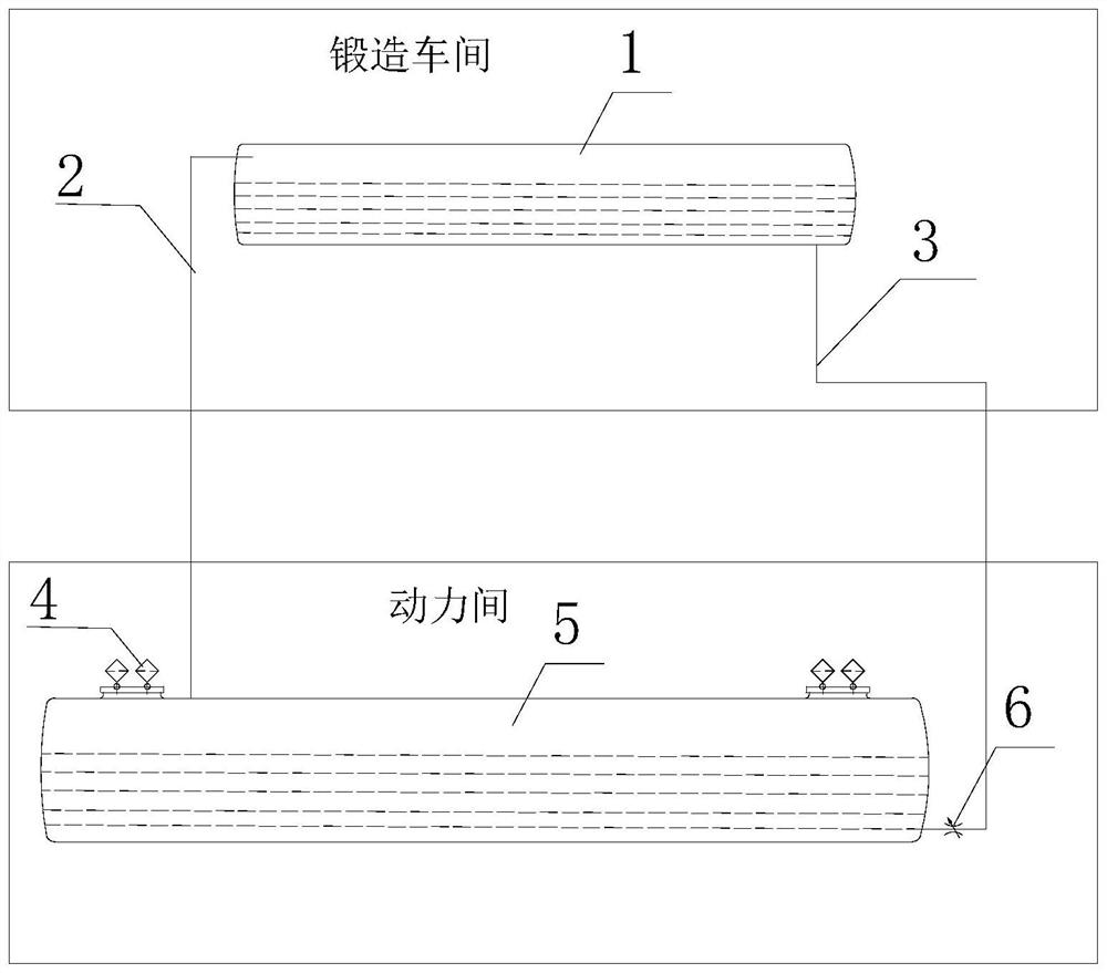
[0030] Such as figure 1 Shown, technical scheme of the present invention is:

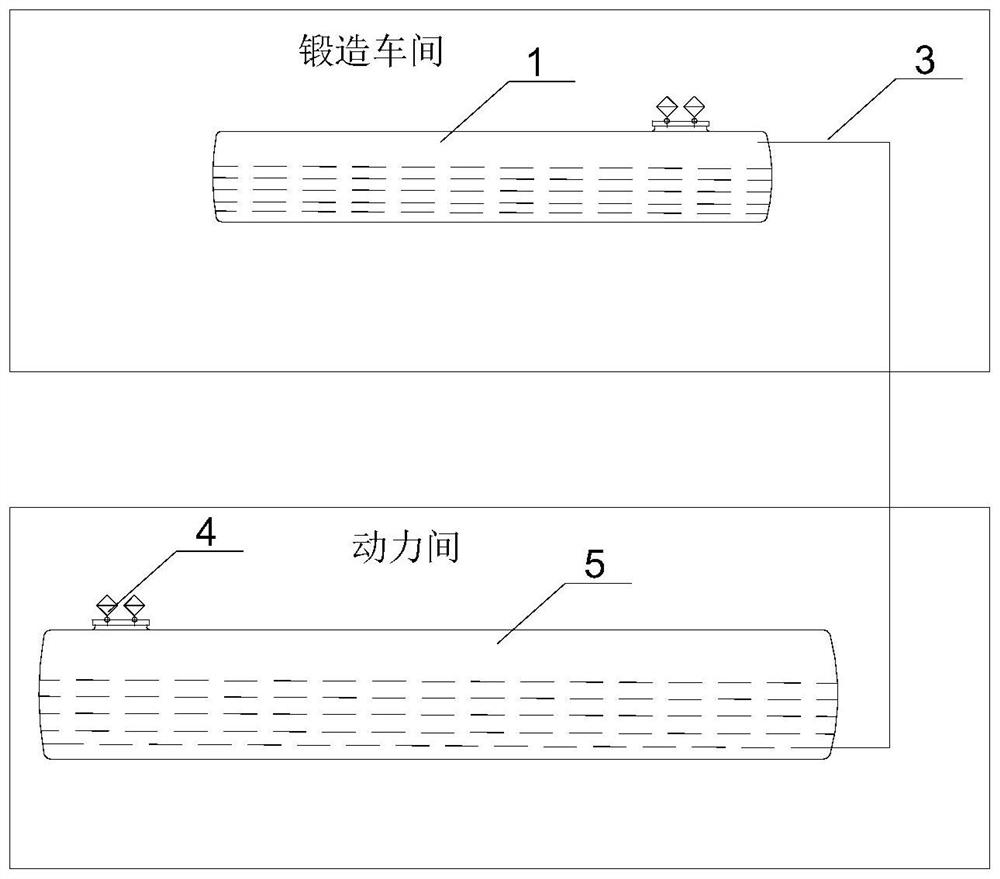
[0031] A liquid filling system for open die forging presses, including a liquid filling oil tank 1 located on the top of the equipment in the forging workshop, and a main oil tank 5 located on the ground of the power room;

[0032] An air filter 4 is arranged on the main oil tank 5;

[0033] The main oil tank 5 communicates with the liquid-filled oil tank 1 through the air pipeline 2;

[0034] The main oil tank 5 communicates with the liquid-filled oil tank 1 through the oil discharge pipeline 3;

[0035] A valve is installed on the oil discharge pipeline 3;

[0036] A controller that controls the opening of the valve according to the requirements of the produ...


PUM


Abstract

The invention discloses a liquid filling system for a free forging press, which belongs to the technical field of free forging presses and comprises a liquid filling oil tank positioned at the top of forging workshop equipment and a main oil tank positioned on the ground of a power room. An air filter is arranged on the main oil tank; the main oil tank is communicated with the liquid filling oil tank through an air pipeline; the main oil tank is communicated with the liquid-filled oil tank through an oil discharge pipeline; a valve is mounted on the oil discharge pipeline; the valve is a pneumatic stop valve. According to the invention, any liquid level height control of the liquid filling oil tank can be realized so as to meet the oil filling and discharging requirements under different production processes, and meanwhile, when danger occurs, the pneumatic stop valve can be quickly opened to quickly empty oil in the liquid filling oil tank so as to avoid fire; an intake and exhaust air filter of the liquid-filled oil tank is omitted, a special air pipe is added to be communicated with the main oil tank to achieve air pressure balance of the liquid-filled oil tank and the main oil tank, and oil discharge resistance caused by the vacuum trend generated when the liquid-filled oil tank discharges oil to the main oil tank and the pressurization trend generated when the oil enters the main oil tank is avoided.

Description

technical field [0001] The invention belongs to the technical field of free forging presses, and in particular relates to a liquid filling system for free forging presses. Background technique [0002] As we all know, the working conditions of the open die forging press are very harsh. The temperature of the hot forging is about 1000 degrees Celsius. During the working process, the forging produces a lot of dust. If the liquid filling system at the top of the press leaks oil, the oil will easily cause a fire when it contacts the hot forging. see figure 2 , When the working environment is dusty, it is easy to enter the oil tank through the air filter of the conventional liquid filling system and pollute the oil. At the same time, the traditional liquid filling system uses a fixed position to discharge oil (that is, the upper part of the side wall of the liquid filled oil tank). All the oil pumped into the oil cylinder by the main oil tank will be pushed into the filled oil...

Claims


Application Information

Patent Timeline
IPC IPC(8): B21J9/12F15B21/041
CPCB21J9/12F15B21/041
Inventor 刘冬冬刘辉杜丽峰祁磊王为全石磊
Owner TIANJIN TIANDUAN PRESS CO LTD
Why Eureka
Try Eureka